Resonant circuit instead of PWM. Pulse width modulation, PWM, PWM, control, regulation, regulator, modulator
8. Pulse width modulation in converters
8.1. General information
The principles of pulse control and modulation are discussed in Chap. 4 on the example of the simplest DC regulator circuit. At the same time, definitions are given for the main types of pulse modulation used in the theory of linear pulse systems, which correspond to the practice of controlling pulsed DC converters.
However, pulse-width modulation of voltages or currents in AC converters has a slightly different definition in power electronics, taking into account the features of PWM when solving problems of converting electricity to alternating current. As defined by IEC 551-16-30, Pulse Width Modulation refers to impulse control in which the width or frequency of pulses, or both, are modulated within a period of the fundamental frequency in order to create a particular shape of the output voltage waveform. In most cases, PWM is carried out in order to ensure a sinusoidal voltage or current, that is, to reduce the level of higher harmonics relative to the fundamental (first) harmonic, and is called sinusoidal. There are the following main methods for ensuring sinusoidality: analog PWM and its modifications; selective (selective) suppression of higher harmonics; hysteresis or delta modulation;
space vector modulation.
The classic variant of organizing an analog sinusoidal PWM is to change the width of the pulses that form the output voltage (current) by comparing a voltage signal of a given shape, called a reference or reference, with a triangular voltage signal that has a higher frequency and is called a carrier signal. The reference signal is modulating and determines the required shape of the output voltage (current). There are many modifications of this method, in which the modulating signals are represented by special functions other than a sinusoid. The lecture notes will cover several basic circuits explaining these PWM methods.
The method of selective suppression of higher harmonics is currently successfully implemented by means of microprocessor controllers based on software. Hysteresis modulation is based on the principles of relay "following" a reference signal, for example, a sinusoidal waveform. In the simplest technical implementation, this method combines the principles of PWM and PFM (pulse frequency modulation). However, by means of special circuitry measures, it is possible to stabilize the modulation frequency or limit the range of its change.
The space vector modulation method is based on converting a three-phase voltage system into a two-phase one and obtaining a generalized space vector. The value of this vector is calculated at times determined by the fundamental and modulating frequencies. It is considered very promising for the control of three-phase inverters, in particular, when used in an electric drive. At the same time, it is in many ways similar to traditional sine-wave PWM.
PWM-based control systems make it possible not only to provide a sinusoidal shape of the averaged values of the voltage or current fundamental harmonic, but also to control the values of its amplitude, frequency, and phase. Since in these cases the converter uses fully controlled switches, it becomes possible to implement the operation of AC (DC) converters together with the AC network in all four quadrants in both rectifying and inverting modes with any given value of the fundamental power factor cosφ in range from -1 to 1. Moreover, with an increase in the carrier frequency, the possibilities of reproducing current and voltage inverters of a given form at the output expand. This allows you to create active filters to suppress higher harmonics.
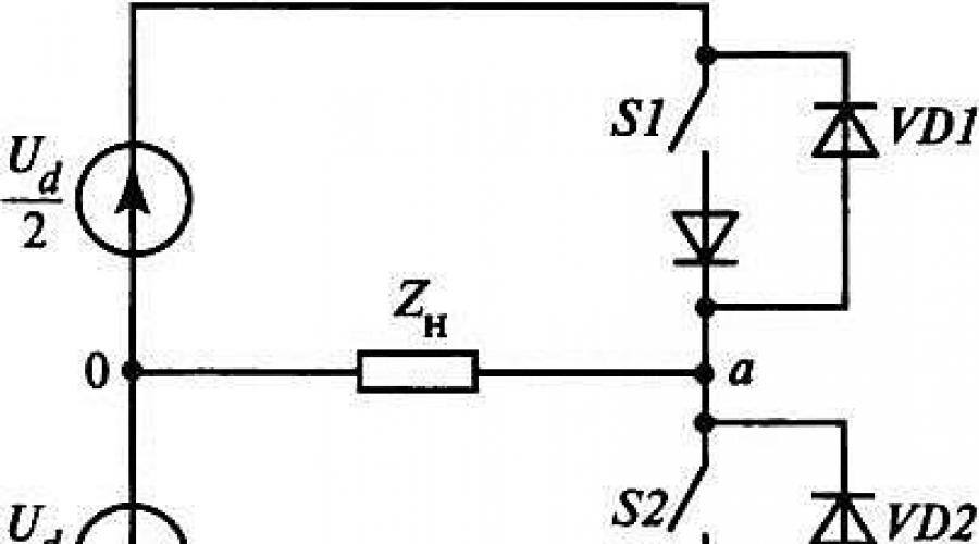
We will consider the main definitions used in the further presentation using the example of applying the first method in a single-phase half-bridge circuit of a voltage inverter (Fig. 8.1, but). In this conditional scheme, the keys S1 And S2 are represented by fully controlled switching elements, supplemented by diodes connected in series and in parallel with them. Serial diodes reflect the unidirectional conduction of keys (for example, transistors or thyristors), while parallel diodes provide conduction of reverse currents with an active-inductive load.
Diagrams of the reference, modulating u M (θ) and carrier u H (θ) signals are shown in fig. 8.1, b. Key control pulse generation S 1 and S 2 is carried out according to the following principle. At u M (θ) > u H(θ) key S 1 is on, a S 2 switched off. At u M(θ)< u H (θ) the states of the keys are reversed: S 2 - enabled, a S 1 - off. Thus, a voltage is formed at the output of the inverter in the form of two polar pulses. In real circuits, to exclude simultaneous conduction of keys S 1 and S 2, a certain delay should be provided between the moments of generation of signals to turn on these keys. Obviously, the pulse width depends on the ratio of signal amplitudes u M (θ) and u H(θ). The parameter characterizing this ratio is called the amplitude modulation index and is determined by the formula (8.1):
, (8.1.)
where U M m and U H m - maximum values of the modulating signal u M (θ) and carrier signal u H(θ), respectively.


Rice. 8.1. Single-phase semi-bridge voltage inverter: but- scheme; b– voltage diagrams for pulse modulation
Carrier frequency u H (θ) is equal to the switching frequency f H keys S 1 and S 2 and usually significantly exceeds the frequency of the modulating signal f M. Frequency ratio f H and f M is an important indicator of the efficiency of the modulation process and is called the frequency modulation index, which is determined by the formula (8.2):
For small values M f signals u M (θ) and u H (θ) must be synchronized to avoid unwanted subharmonics. B as maximum value My, which determines the need for synchronization, is set M f = 21. Obviously, with synchronized signals and the coefficient M f is a constant.
From the diagram in fig. 8.1 it can be seen that the amplitude of the first harmonic of the output voltage U am 1, taking into account (8.1), can be represented in the following form (8.3):
![]() (8.3)
(8.3)
According to (8.3) for M a = 1 the amplitude of the first harmonic of the output voltage is equal to the height of the half-wave rectangle U d/2. The characteristic dependence of the relative value of the first harmonic of the output voltage on the value of M a is shown in fig. 8.2, which shows that the change M a from 0 to 1 is linear and depends on the amplitude U am 1 . Limit value M a is determined by the principle of the type of modulation under consideration, according to which the maximum value U am 1 is limited by the height of a rectangular half-wave equal to U d/2. With a further increase in the coefficient M a modulation leads to a non-linear increase in the amplitude U am 1 to the maximum value determined by the formation of a square-wave voltage at the output of the inverter, which subsequently remains unchanged.
The expansion of a rectangular function in a Fourier series gives the maximum value (8.4):
![]() (8.4)
(8.4)
This value is limited by the index value M a, varying in the range from 0 to about 3. It is obvious that the function on the interval a-b of values from 1 to 3.2 is non-linear (Fig. 8.2). The mode of operation in this section is called over modulation.
Meaning M f determined by the choice of carrier signal frequency u H (θ) and significantly affects the technical characteristics of the converter. With increasing frequency, switching losses in the power switches of the converters increase, but at the same time, the spectral composition of the output voltage improves and the solution of the problem of filtering higher harmonics due to the modulation process is simplified. An important factor in choosing the value f H in many cases is the need to ensure its value in the audio frequency range of more than 20 kHz. When choosing f H should also take into account the level of operating voltages of the converter, its power and other parameters.

Rice. 8.2. Dependence of the relative value of the amplitude of the fundamental harmonic of the output voltage on the amplitude modulation index for a single-phase half-bridge circuit
The general trend here is an increase in the values of M f low power and low voltage converters and vice versa. Poet choice M f is a multiobjective optimization problem.
Pulse modulation with stochastic process. The use of PWM in converters is associated with the appearance of higher harmonics in modulated voltages and currents. Moreover, in the spectral composition of these parameters, the most significant harmonics occur at frequencies that are multiples of the frequency modulation index M f and harmonics grouped around them at side frequencies with decreasing amplitudes. Higher harmonics can give rise to the following main problems:
the occurrence of acoustic noise;
deterioration of electromagnetic compatibility (EMC) with other electrical devices or systems.
The main sources of acoustic noise are electromagnetic components (chokes and transformers), which are affected by current and voltage containing higher harmonics with frequencies in the audio range. It should be noted that noise can occur at certain frequencies, where higher harmonics are at their maximum. Factors that cause noise, such as the phenomenon of magnetostriction, complicate the resolution of the EMC problem. EMC problems can occur over a wide frequency range, depending on the severity of the electromagnetic interference level of electrical devices. Traditionally, design and technological solutions have been used to reduce noise levels, and passive filters have been used to ensure EMC.
Methods associated with changing the nature of the spectral composition of modulated voltages and currents are considered as a promising direction for solving these problems. The essence of these methods is to equalize the frequency spectrum and reduce the amplitude of pronounced harmonics due to their stochastic distribution over a wide frequency range. This technique is sometimes called "smearing" the frequency spectrum. Interference energy concentration decreases at frequencies where harmonics can be at their highest. The implementation of these methods is not related to the impact on the components of the power part of the converters and in most cases is limited by software tools with a slight change in the control system.
Let us briefly consider the principles of implementing these methods. PWM is based on the change in the duty cycle γ= t And / T n, where t u - pulse duration; T n- the period of its formation. Usually these values, as well as the position of the pulse on the interval of the period T n are constant in steady state. PWM results are defined as integral averaged values. In this case, the deterministic values of t and and including the pulse position cause an unfavorable spectral composition of the modulated parameters. If these quantities are given a random character while maintaining a given value of γ, then the processes become stochastic and the spectral composition of the modulated parameters changes. For example, such a random character can be given to the position of the impulse t and on the period interval T n or provide a stochastic change of the latter. For this purpose, a random number generator can be used, which acts on the master modulation frequency generator f n =1/T n. Similarly, you can change the position of the pulse on the interval T n with mathematical expectation equal to zero. The average integral value γ must remain at the level set by the control system, as a result of which the spectral composition of higher harmonics in the modulated voltages and currents will be equalized.
Questions for self-control
1. List the main PWM methods to provide a sinusoidal current or voltage.
2. What is the difference between unipolar voltage modulation and bipolar?
3. List the main PWM parameters.
4. What is the purpose of using PWM with stochastic processes?
Pulse-width modulation (PWM) is a signal conversion method in which the pulse duration (duty cycle) changes, while the frequency remains constant. In English terminology, it is referred to as PWM (pulse-width modulation). In this article, we will understand in detail what PWM is, where it is used and how it works.
Application area
With the development of microcontroller technology, new opportunities have opened up for PWM. This principle has become the basis for electronic devices that require both adjustment of output parameters and maintaining them at a given level. The pulse-width modulation method is used to change the brightness of light, the speed of rotation of engines, as well as to control the power transistor of pulse-type power supplies (PSU).
Pulse-width (PW) modulation is actively used in the construction of LED brightness control systems. Due to the low inertia, the LED has time to switch (flash and go out) at a frequency of several tens of kHz. Its operation in a pulsed mode is perceived by the human eye as a constant glow. In turn, the brightness depends on the duration of the pulse (the open state of the LED) during one period. If the pulse time is equal to the pause time, that is, the duty cycle is 50%, then the brightness of the LED will be half of the nominal value. With the popularization of 220V LED lamps, the question arose of increasing the reliability of their operation with an unstable input voltage. The solution was found in the form of a universal microcircuit - a power driver operating on the principle of pulse-width or pulse-frequency modulation. A circuit based on one of these drivers is described in detail.
The mains voltage supplied to the input of the driver microcircuit is constantly compared with the in-circuit reference voltage, forming a PWM (PFM) signal at the output, the parameters of which are set by external resistors. Some microcircuits have an output for supplying an analog or digital control signal. Thus, the operation of the pulse driver can be controlled using another SHI converter. Interestingly, the LED does not receive high-frequency pulses, but a current smoothed by a choke, which is an indispensable element of such circuits.
The massive use of PWM is reflected in all LCD panels with LED backlighting. Unfortunately, in LED monitors, most of the SHI converters operate at a frequency of hundreds of Hertz, which negatively affects the vision of PC users.
The Arduino microcontroller can also operate in PWM controller mode. To do this, call the AnalogWrite () function with the values \u200b\u200bbetween 0 and 255 indicated in brackets. Zero corresponds to 0V, and 255 to 5V. Intermediate values are calculated proportionally.
The ubiquity of devices operating on the PWM principle has allowed mankind to move away from linear-type transformer power supplies. As a result, an increase in efficiency and a decrease in the weight and size of power sources by several times.
The PWM controller is an integral part of a modern switching power supply. It controls the operation of the power transistor located in the primary circuit of the pulse transformer. Due to the presence of a feedback circuit, the voltage at the PSU output always remains stable. The slightest deviation of the output voltage through the feedback is fixed by a microcircuit, which instantly corrects the duty cycle of the control pulses. In addition, a modern PWM controller solves a number of additional tasks that improve the reliability of the power supply:
- provides the mode of soft start of the converter;
- limits the amplitude and duty cycle of the control pulses;
- controls the input voltage level;
- protects against short circuit and overtemperature of the power switch;
- puts the device into standby mode if necessary.
The principle of operation of the PWM controller
The task of the PWM controller is to control the power switch by changing the control pulses. When operating in the key mode, the transistor is in one of two states (fully open, fully closed). In the closed state, the current through the p-n junction does not exceed a few μA, which means that the dissipation power tends to zero. In the open state, despite the high current, the resistance of the p-n junction is excessively low, which also leads to insignificant heat losses. The greatest amount of heat is released at the moment of transition from one state to another. But due to the short time of the transition process compared to the modulation frequency, the power loss during switching is negligible.
Pulse width modulation is divided into two types: analog and digital. Each of the types has its own advantages and can be implemented in circuitry in different ways.
Analog PWM
The principle of operation of an analog SHI modulator is based on comparing two signals whose frequency differs by several orders of magnitude. The comparison element is an operational amplifier (comparator). A sawtooth voltage of a high constant frequency is applied to one of its inputs, and a low-frequency modulating voltage with a variable amplitude is fed to the other. The comparator compares both values and generates rectangular pulses at the output, the duration of which is determined by the current value of the modulating signal. In this case, the PWM frequency is equal to the frequency of the sawtooth signal.
Digital PWM
Pulse width modulation in digital interpretation is one of the many functions of the microcontroller (MC). Operating exclusively with digital data, the MK can generate either a high (100%) or low (0%) voltage level at its outputs. However, in most cases, to effectively control the load, the voltage at the output of the MK must be changed. For example, adjusting the speed of rotation of the engine, changing the brightness of the LED. What to do to get any voltage value in the range from 0 to 100% at the output of the microcontroller?
The issue is solved by using the method of pulse-width modulation and using the oversampling phenomenon, when the specified switching frequency is several times higher than the response of the controlled device. By changing the duty cycle of the pulses, the average value of the output voltage changes. As a rule, the whole process takes place at a frequency of tens to hundreds of kHz, which makes it possible to achieve smooth adjustment. Technically, this is implemented using a PWM controller - a specialized microcircuit, which is the "heart" of any digital control system. The active use of PWM-based controllers is due to their undeniable advantages:
- high signal conversion efficiency;
- work stability;
- saving energy consumed by the load;
- low cost;
- high reliability of the entire device.
There are two ways to get a PWM signal at the pins of the microcontroller: hardware and software. Each MK has a built-in timer that is able to generate PWM pulses on certain pins. This is how the hardware implementation is achieved. Getting a PWM signal using software commands has more options in terms of resolution and allows you to use more pins. However, the software method leads to a high loading of the MK and takes up a lot of memory.
It is noteworthy that in digital PWM, the number of pulses per period can be different, and the pulses themselves can be located in any part of the period. The output signal level is determined by the total duration of all pulses per period. It should be understood that each additional pulse is a transition of the power transistor from the open state to the closed state, which leads to an increase in losses during switching.
An example of using a PWM controller
One of the implementation options for a simple PWM controller has already been described earlier in. It is built on the basis of a microcircuit and has a small strapping. But, despite the simplicity of the circuit, the regulator has a fairly wide range of applications: control circuits for the brightness of LEDs, LED strips, adjusting the speed of rotation of DC motors.
Read also
With PWM, the sign of the analog modeling signal b(t) (Figure A) changes the width (pulse duration (c)) of the subcarrier with a constant amplitude and repetition rate.
PWM is sometimes called long pulse modulation DIM.
Distinguish ONE- and DOUBLE-SIDE PWM.
With one-sided PWM, the change in the pulse width occurs only due to the shift of the pulse cutoff (PWM-1) (Figure B)
And with a double-sided cut and the front of the pulse PWM-2 (Figure D)
The most widely used PWM-1

And we will assume that the modeling signal
changes according to the harmonic law, according to which
the pulse width is:
Where  - pulse duration deviation
Substituting this value  to the previous
expression we get the spectral signal of the PWM signal.
It is most convenient to perform a PWM signal modulator on integrated circuits (ICs)

Input 2 is fed with a pulsed subcarrier
Input 5 – analog modeling signal b(t)
PWM demodulator is most often LPF
27. Phase-pulse modulation. PIM signal modulators.
With PIM, according to the law of the simulated analog signal b(t), only the time position of the subcarrier video pulses changes, while their amplitude and duration remain unchanged.
If you differentiate the PWM signal in time, then positive and negative pulses are obtained.
A positive pulse corresponds to the front of the PWM signal, and a negative pulse corresponds to its cutoff.
With one-way PWM, the positive pulses are stationary, and the negative ones are shifted in proportion to the modeling signal b(t) along the time axis.
The stationary pulses can be eliminated with a resistive half-wave rectifier and the remaining pulses are PPM signals.
The PWM signal modulator in this case consists of a PWM modulator to the output of which a differentiating device DU and a half-wave rectifier OB are connected. (see picture)

The analytical expression of the signal PIM has the form:

 - pulse amplitude
 -function describing the envelope of the measuring pulse.
 - doviation of the time position of the measuring pulse
 - the value of the transmitted message at the moment of time
The frequency spectrum of PIM signals is analytically difficult to represent
The approximate value for the amplitude of the transmitted harmonic signal in the PIM spectrum is:

Where  - message frequency
 - pulse duration
The amplitude of the transmitted signal in the PWM spectrum is very small (much smaller than in the AIM and PWM spectra and is a function of the modeling frequency  , i.e. distorted).
Therefore, demodulation of PPM signals with a low-pass filter is not directly possible.
They are converted into AIM or PWM signals.
28. Frequency-pulse modulation. Chim signal detectors.
The detector can be made according to the scheme
Where F- channel filter; JSC- amplitude limiter; DC-diff. chain; DV-two-half-wave rectifier with active load; OV- single vibrator; D-detector with voltage doubling; LPF-low pass filter.
The operation of the detector is explained with the help of timing diagrams.

After passing through the narrowband circuits of the communication channel, the PFM signal becomes similar to the analog FM signal. By the AO block, it is deeply limited in amplitude on both sides so that the same rectangular pulses of different repetition rates and durations occur at its output. In the DC block, these pulses are differentiated in time, as a result of which, at its output, UDC (t) represents fronts and cuts. The latter are very narrow bipolar pulses, which are converted in the DW block into unipolar Umot(t), thereby doubling the repetition rate. In the OB block, identical rectangular pulses of the same duration, but of different repetition rates, are formed, which are fed to the input of the D block. Schematic diagram of the D block:

At the output of the circuit, there is a transmitted analog signal Ud(t). In some cases, the OB block is excluded. The high stability of the parameters of this detector led to its wide application even for analog FM signals.
Pulse width modulation. Description. Application. (10+)
Pulse width modulation
One of the approaches to reduce the heating losses of the power elements of the circuits is the use of switching modes of operation. In such modes, the power element is either open, then there is practically zero voltage drop on it, or closed, then zero current flows through it. Dissipated power is equal to the product of current and voltage. More about this at the link. In this mode, it is possible to achieve an efficiency of more than 80%.
To obtain a signal of the desired shape at the output, the power switch opens for a certain time proportional to the desired output voltage. This is pulse-width modulation (PWM, PWM). Further, such a signal, consisting of pulses of different widths, enters a filter consisting of a choke and a capacitor. At the output of the filter, an almost perfect signal of the desired shape is obtained.
Application of Pulse Width Modulation (PWM)
Unfortunately, errors occur periodically in articles, they are corrected, articles are supplemented, developed, new ones are being prepared. Subscribe to the news to stay informed.
If something is not clear, be sure to ask!
Ask a Question. Article discussion. messages.
More articles
Power powerful pulse transformer. Payment. Calculate. Online. Oh...
Online calculation of a power pulse transformer....
How not to confuse plus and minus? Reverse polarity protection. Scheme...
Reverse polarity protection circuit (polarity reversal) of chargers...
Resonant inverter, voltage boost converter. The principle of r...
Assembly and adjustment of the step-up voltage converter. Description of the working principle...
Oscillatory circuit. Scheme. Payment. Application. Resonance. Resonant...
Calculation and application of oscillatory circuits. Resonance phenomenon. Sequential...
A simple pulse forward voltage converter. 5 - 12 w...
Diagram of a simple voltage converter to power an operational amplifier....
Power factor corrector. Scheme. Payment. Operating principle....
Power factor corrector circuit...
Do-it-yourself bespereboynik. UPS, UPS do it yourself. Sine, sinusoid...
How to make an uninterruptible switch yourself? Purely sinusoidal output voltage, with...
Power powerful pulse transformer, choke. Winding. Make...
Techniques for winding a pulse choke / transformer ....
Why do the lights go out so slowly in movie theaters?
-Because the projectionist unplugs the plug very slowly.
Introduction to pulse-width modulation.
Earlier, we learned how to control the LED by changing the state of the GPIO port. We learned how to control the duration and frequency of the pulses, thanks to which we got various lighting effects. We made sure that if you change the state of the port with an audio frequency, you can get different
sounds, mastered frequency modulation ...
And what happens if we change the level of the port with an audio frequency, but instead of a speaker, we connect our old experimental friend - an LED?
Do an experiment. Modify our blink.c program so that the LED turns on and off 200 times per second, at a frequency of 200 Hz. To do this, just change the parameters of the delay() function. To find out what delays to enter, it is enough to calculate the oscillation period T. T=1/f. And since f is equal to 200 Hz, then T \u003d 1/200 \u003d 0.005 seconds, or 5 milliseconds. For these 5 milliseconds, we must have time to turn on the LED and turn it off 1 time. Since 5 by 2 is not divisible, let's take the LED glow time of 2 ms, and the non-glow time of 3 ms. 2+3=5, i.e. the full period of one oscillation will remain 5ms. Now let's change the program: replace delay(500) with delay(2) and delay(3) for on and off
LEDs respectively.
Let's compile the program and run it. If you still have a speaker installed in the circuit, you will hear a low sound, and if you replace the speaker with an LED, you will see a continuously lit LED. In fact, the LED blinks, of course, but it does it so fast that the eye no longer notices this blinking and perceives
its like a continuous glow. But the diode does not seem to shine as brightly as it used to burn with us. For comparison, you can run our very first program, where the LED was constantly on, and compare the brightness of the LED in both cases. Let's see why this happens and how it can be used.
Remember, in the very first part, we calculated the current-limiting resistor to power the LED? We know that the LED has a working current at which it glows most brightly. If this current is reduced, then the brightness of the LED will also decrease. And when we start quickly turning the LED on and off, then
its brightness becomes dependent on the average current (Iср) for the oscillation period. For a pulse (P-shaped) signal that we generate at the output of the GPIO port, the average current will be proportional to the ratio of t1 to t2. Namely: Iср=In x t1/t2, where In is the rated current of the LED, which we set to 10mA thanks to the resistor. At rated current, the LED glows most brightly. And in our case, Iср = 10 x 2/3 = 6.7 mA. We see that the current has become less, so the LED began to burn less brightly. In this formula, the ratio t1/t2 is called duty cycle D.
The larger this coefficient, the greater the average current value. We can change this ratio from 0 to 1, or from 0% to 100%. So, we can change the average current within these limits. It turns out that in this way we can adjust the brightness of the LED from maximum to completely off! And although the voltage at the output of our port can still only be either +3.3V or 0V, the current in our circuit can change. And by changing this current, we can easily control our Malinka. This kind of control is called Pulse Width Modulation, or simply PWM. In English it sounds like PWM, or P pulse-width modulation. PWM is a constant frequency pulse signal with a variable duty cycle. Such a definition as a pulse signal of constant frequency with a variable duty cycle is also used. The duty cycle S is the reciprocal of the duty cycle and characterizes the ratio of the pulse period T to its duration t1.
S=T/t1=1/D.
Well, for us, to consolidate our knowledge, it remains to write a program that will smoothly turn on and off our LED. The process of changing the brightness of the glow is called dimming.
I got it like this:
dimmer.c
// The program smoothly changes the brightness of the LED
// LED connected to port P1_03#include
int main()
{
if (!bcm2835_init()) return 1;
Bcm2835_gpio_fsel(PIN,BCM2835_GPIO_FSEL_OUTP);
//Set port P1_03 to output unsigned int t_on, t_off;
// t_on duration of the on state = t1, and t_off- of the off state = t2
Int d = 100, i, j, flag=0; // d- duty cycle in percent, i and j, auxiliary variables for organizing cycles, flag- if =0 the LED goes out, if =1 it flares up
int a=10; // number of complete work cycles
while (a)
{
for (j=100; j!=0; j--) //change the fill factor from 100% to 0%
{
t_on=50*d; // find t1
t_off=50*(100-d); // find t2
if (flag==0) d=d-1; // if the LED is fading, reduce the duty cycle
if (flag==1) d=d+1; // if the LED lights up, increase the duty cycle
For (i=10; i!=0; i--) //transfer 10 pulses to the LED with calculated parameters t1 and t2
{
bcm2835_gpio_write(PIN, LOW);
delayMicroseconds(t_on);
bcm2835_gpio_write(PIN, HIGH);
delayMicroseconds(t_off);
}
If (d==0) flag=1; // if the LED is off, start turning it on
if (d==100) flag=0; // if the LED has reached the maximum glow, we start to extinguish it
}
A--;
}
return(!bcm2835_close()); // Exit the program
}
We save the program under the name dimmer.c, compile and run.
As you can see, now our LED is slowly going out and slowly flaring up. This is how PWM works. Pulse width modulation is used in many areas. This includes controlling the brightness of lamps and LEDs, controlling servos, regulating voltage in switching power supplies (which, for example, are in your computer), in digital-to-analog and analog-to-digital converters, etc. By the way, if we return to our speaker circuit, then with the help of PWM you can control the volume of the signal, and by changing the frequency, its tone.
Remember the old anecdote from the preface to this part, about the projectionist slowly pulling the plug out of the socket? Now we know that this projectionist, in order to smoothly turn off the light, must, on the contrary, very quickly insert and pull out the plug from the socket.
This is where we will end this lesson. It only remains to add that PWM is used so often in various applications that processor equipment manufacturers often build a PWM controller directly into the processor. Those. you set the parameters of the signal you need to the processor, and the processor itself, without your help, issues the signal you need. At the same time, without spending any software resources on the generation of this signal. Bcm2835 also has built-in hardware PWM. And this PWM is an alternate feature of GPIO port 18, or P1-12. To use hardware PWM, we must set the P1-12 port to ALT5 mode and set the processor parameters. But that's a completely different story...