LED garland on attiny2313 circuits. LED garland on the microcontroller
This microcontroller led string project is good for beginners. The scheme is distinguished by its simplicity and contains a minimum of elements.
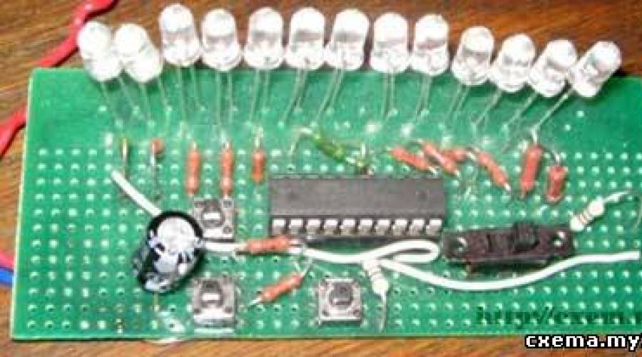
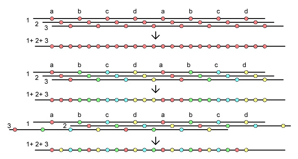
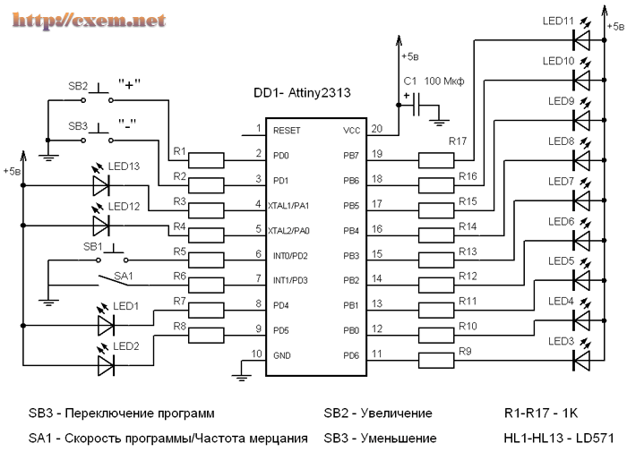
This device controls 13 LEDs connected to the ports of the microcontroller. As a microcontroller, an ATMEL MK is used: ATtiny231320PI .. Due to the use of an internal generator, pins 4 and 5 are used as additional ports of the microcontroller PA0, PA1. The circuit provides the execution of 12 effect programs, 11 of which are individual combinations, and the 12th program is a sequential one-time repetition of the previous effects. Switching to another program is carried out by pressing the SB1 button. Effects programs include running single fire, rising fire, running shadow and more.
The device has the ability to adjust the speed of changing combinations during the execution of the program, which is carried out by pressing the buttons: SB2 - increase the speed and SB3 - decrease the speed, provided that the SA1 switch is in the “Program speed” position. It is also possible to adjust the frequency of the LED burning (from a stabilized glow to a slight flicker), which is carried out by pressing the buttons: SB2 - decrease (to flicker) and SB3 - increase, provided that the SA1 switch is in the “Flicker frequency” position. At switch SA2, the closed position corresponds to the mode for adjusting the speed of program execution, and the open position corresponds to the mode for adjusting the frequency of LED burning.
The numbering order of the LEDs in the circuit corresponds to their firing order when the program is executed. If necessary, the RESET pin can be used for reset, but it is not used as a PA2 port. In the device, during programming, a clock frequency of 8 MHz from the internal generator (fuses CKSEL3..0 - 0100) was selected. Although it is possible to use a frequency of 4 MHz (fuses CKSEL3..0 - 0010) with corresponding changes in the time intervals of the circuit.
The type of LEDs indicated in the diagram was used in the prototype, any LEDs with a supply voltage of 2-3 volts are suitable for the circuit, resistors R1-R17 can be used to adjust the brightness of the LEDs. 
Documentation (Datashit) for MK ATtiny231320PI
Firmware HEX, as well as program files in assembler, you can
download here (30 kb) .
Video demonstration of the operation of the device (enumeration of all effects): http://filearchiv.ru/2140780
Video demonstration of the device operation (changing the speed of execution of effect programs): http://filearchiv.ru/2140535
Video demonstrating the operation of the device (changing the frequency of LED flicker): http://filearchiv.ru/2140747
This microcontroller led string project is good for beginners. The scheme is distinguished by its simplicity and contains a minimum of elements.
This device controls 13 LEDs connected to the ports of the microcontroller. As a microcontroller, an MK from ATMEL is used: . Due to the use of an internal generator, pins 4 and 5 are used as additional ports of the microcontroller PA0, PA1. The circuit provides the execution of 12 effect programs, 11 of which are individual combinations, and the 12th program is a sequential one-time repetition of the previous effects. Switching to another program is carried out by pressing the SB1 button. Effects programs include running single fire, rising fire, running shadow and more.
The device has the ability to adjust the speed of changing combinations during the execution of the program, which is carried out by pressing the buttons: SB2 - increase the speed and SB3 - decrease the speed, provided that the SA1 switch is in the “Program speed” position. It is also possible to adjust the frequency of the LED burning (from a stabilized glow to a slight flicker), which is carried out by pressing the buttons: SB2 - decrease (to flicker) and SB3 - increase, provided that the SA1 switch is in the “Flicker frequency” position. At switch SA2, the closed position corresponds to the mode for adjusting the speed of program execution, and the open position corresponds to the mode for adjusting the frequency of LED burning.
The numbering order of the LEDs in the circuit corresponds to their firing order when the program is executed. If necessary, the RESET pin can be used for reset, but it is not used as a PA2 port. In the device, during programming, a clock frequency of 8 MHz from the internal generator (fuses CKSEL3..0 - 0100) was selected. Although it is possible to use a frequency of 4 MHz (fuses CKSEL3..0 - 0010) with corresponding changes in the time intervals of the circuit.
The type of LEDs indicated in the diagram was used in the prototype, any LEDs with a supply voltage of 2-3 volts are suitable for the circuit, resistors R1-R17 can be used to adjust the brightness of the LEDs.

You can download the HEX firmware, as well as the program files in assembler, below
List of radio elements
| Designation | Type of | Denomination | Quantity | Note | Score | My notepad |
|---|---|---|---|---|---|---|
| DD1 | MK AVR 8-bit | ATtiny2313 | 1 | To notepad | ||
| C1 | electrolytic capacitor | 100uF 10V | 1 | To notepad | ||
| R1-R17 | Resistor | 1 kOhm | 17 | To notepad | ||
| LED1-LED13 | Light-emitting diode | LD571 | 13 | To notepad | ||
| SB1-SB3 | Button | 3 | To notepad | |||
| SA1 | Switch | 1 |
The New Year holidays are approaching and on this occasion I want to do something bright and festive! Decided, here, to make a New Year's garland. What could be brighter and more festive than a New Year's garland? :). I decided to make a garland not simple, but heaped up! 12 channels plus IR remote control. In order not to make a garland from scratch, it was decided as donors internal organs spare parts to use ready-made Chinese garlands. This makes sense for the following reasons:
- the cost of garlands, let's be honest, the cost is a penny. Try to buy wires, LEDs, spare parts for the same money ... And if you do not take an LED garland as a goal, then light bulb garlands are now sold almost for nothing;
- an important factor - ready-made lines of LEDs soldered to a heap. Soldering yourself, putting in heat shrinks, making mistakes, redoing 12 lines is a rather dreary job;
- yet, I don’t know about you, but I have a certain number of non-working garlands lying around (they are often dragged to me to repair - they settle down) you can not spend money on new ones at all, but collect them from what is.
For starters, watch the video:
ATTENTION!
dangerous voltage 220V!
LIFE THREATENING!
THAT'S WHY:
If you realize the danger assembling such a garland and undertake to comply with safety regulations when working with dangerous voltage, read on for how to assemble a super garland.
1 Garland patients.
As victims, 3 new LED garlands were bought - here they are beauties 🙂
The cost is $ 3 per piece (100 LEDs). But if the Chinese do not save, then they will change themselves! In garlands, in fact, it turned out to be 3 channels each. That is, the controller itself is four-channel, but there are three thyristors and three LED lines. In order to disguise such a disgrace, the Chinese interfere with LEDs of two colors in one line. In short, I had to buy another one :(. But this is not the limit of savings, often there are two channels in general! Be careful - open the box and see how much thyristors cost.
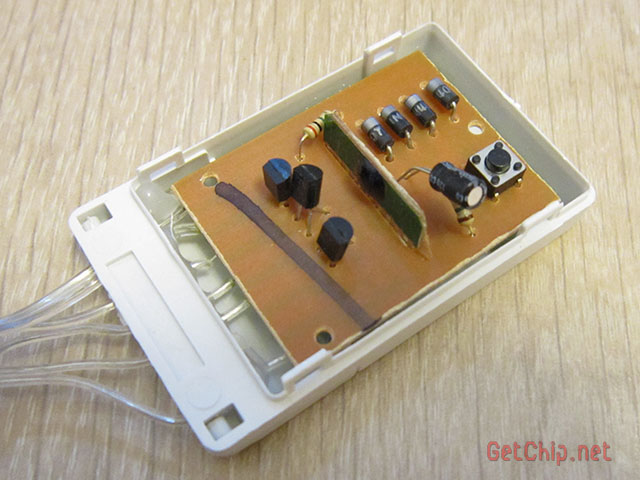
Of the original controllers for the improved garland, resistors, rectifier diodes, thyristors, a button, and boxes will be used. You will need to buy a little more than a dozen resistors, a couple of capacitors, an ATtiny2313 microcontroller and other little things.
2 Scheme.
Here is the diagram of the original garland:
It can be seen from the diagram that the dimming of the LED channels is carried out by thyristors PCR406
Datasheet for thyristor PCR406
I see no reason to change them to something else. To form the supply voltage of the original controller, a quenching resistor is used (the quenching resistor together with the internal resistance of the controller form a voltage divider). The decision is contradictory, but in this case it is justified by cheapness (the controller current is insignificant and the power allocated to the resistor is very small). After weighing the pros and cons of such a decision, I decided to do something similar in my scheme. True, the current of the ATtiny2313 (within 8mA) is much higher than the original controller, but still allows the use of quenching resistors.
Diagram of the new garland controller:
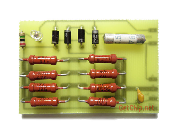
6 Assemble the power supply board.
Before assembling the power supply board, certain measurements must be taken to calculate the value of the quenching resistors. To do this, we connect the soldered controller board with a firmware microcontroller to an EXTERNAL source of 5 volts (+5v and -5v pads) and measure the current consumed. It is not necessary to connect the LED lines, they practically do not affect the current consumption. For a typical ATtiny2313 microcontroller without letter indices, the current consumption should be about 7 - 9 mA. For an ATtiny2313 microcontroller with indices (maybe A, P...) the current will be different.
Based on the obtained current consumption (Ipotr), we calculate the resistance of the quenching resistors in the battery (we take the larger one from the standard series):
R = 430 / Icon
For example, my current consumption was 9 mA, which means R \u003d 430 / 0.009 \u003d 47777 Ohms (take 47 kOhm).
The pile of quenching resistors is made in order to distribute the dissipated power and reduce heating. Resistors must be at least 0.5 W (preferably 1 W each).
Rectifier diodes and a quenching resistor migrate from the original circuit, the rest will have to be purchased. We put the finished board in the body of the garland.
We connect the power supply and controller boards (we take the wires and plug from the original garland). Do not forget to fix the wires soldered to the boards with hot glue, since the wires used by the Chinese, to put it mildly, are shit and can fall off at any moment.
7 Formation of LED lines.
Here's what you have to tinker with, so it's with the formation of 12 channels of LED lines. It will be necessary to assemble a common bundle with twelve lines (plus a common wire) from three bundles (and in the case of three channels in a garland - four bundles) of the original garlands. The garlands need not just be twisted together, but make sure that the LEDs of all twelve channels are arranged in series one after the other. In addition, if the garland is multi-colored, you need to make sure that the colors mix as much as possible.
In general, single-color garlands are better for better visualization of effects, but multi-colored garlands, perhaps, win for creating a brighter image. Here you have to decide either more expressive effects or a more colorful impression.
It takes a long time to explain in words - look at the pictures or think for yourself how you twist the bundles:
The bundles are twisted - now we solder them to the controller in such a way that the channel LEDs follow each other in series.
8 Description of the work of the garland.
When you turn on the garland in the network, it immediately starts working with a random effect. In the process, the effects will randomly change each other. If you press the button, then the effects will sequentially replace each other in turn:
1 Wave
2 shooting star
3 sparks
4 Slow overflows
5 Running lights
6 twinkling lights
7 Everything is on-going out
8 Everything is on fire
0 All off
When selecting an effect with the button, it is delayed for a longer time, but later the effects will again begin to replace each other.
The operation from the remote control is similar to the operation of the button on the controller (we press the button on the remote control - the effects change sequentially). To study the button of any IR remote control, you need to hold down the button on the controller until the garland goes out (about 3 seconds), then you need to press the selected button on the remote control. The button code will be written to non-volatile memory and the garland will return to the effects. Since the code is stored in non-volatile memory, the garland will "remember" the remote control even after disconnecting from the network.
Finally, I think it is not superfluous to recall:
ATTENTION!
The garland circuit is not galvanically isolated from the network dangerous voltage 220V!
Touching any conductive part of the garland included in the network
LIFE THREATENING!
THAT'S WHY:
- if you are poorly versed in electricity - do not repeat this design;
- any actions (soldering, measurements, etc.) with the circuit must be performed only after disconnecting from the network;
- programming of the microcontroller must be done either separately from the board (for example, in a breadboard specially assembled for this), or by powering the garland board from an external voltage source of 5 volts (for example, from batteries);
- the finished structure must be well insulated and inaccessible to small children and animals;
- be careful when assembling the structure!
And here are examples, so to speak, live:
Submit yours and I'll add it here.
Christmas tree from AndreevKV. It turned out big! 🙂
Christmas tree from BOYka59. All my friends and especially the children are delighted with it)
And further!
Happy New Year!
All good mood and happy holidays!
Update 1 (2013)
I didn’t particularly plan to do something with this garland, since there is no time for this this year, but at the request of readers, I still decided on a small update!
Changed a little.
Added 6 new effects:
- a wave running in different directions from 2 LEDs
- sequential filling and descending
— successive filling and decreasing with a variable traveling wave
- random fill and delete
- random filling and removal with a variable traveling wave
- aggressive flicker
The duration of the effect when forced switching (remote control or button) is almost doubled.
That's actually all. The scheme and fuses remained the same. You need to re-upload the new firmware.
- 12-channel supergarland (2013 update)
- Supergarland update source
Happy New Year 2014!!! 😉
Super garland options from blog readers
Sergei Cherniy (Black_S)
The garland is implemented on a single board using SMD components
TsMU/SDU on the microcontroller (8 channels)
This device combines color music (CMU) and a dynamic light device (SDU) for 8 channels, with many lighting effects. The outputs of the device are designed to connect a sufficiently powerful load.
The division of frequencies into channels of the DMU is purely software and very simple, the PIC microcontroller PIC16F628A is used. The number of timer / counter pulses is counted for a strictly defined period of time, and depending on the value of this counter, one or another LED turns on.
And here is the device diagram:

The buttons allow:
- Select mode - CMU/SDU. In the SDU mode, even if there is a signal at the input, only the main program of the light-dynamic device works. In DMU mode, if there is no signal, then the selected SDU effect will be played as a background mode.
- Select the SDU effect. The button cycles through all possible effects of the light-dynamic device.
- Increase and decrease speed. These buttons control the speed of the effects of the CDS, they have no effect on the DMC.
The printed circuit board is single-sided, quite simple. The LEDs installed on the board are debugging and serve simply as an additional visualization device.
As colored spotlights, I used ready-made spotlights from a hardware store. Of these, I removed the standard bulb holder and installed a matrix of 37 bright LEDs there. Each spotlight has its own color - red, green, blue, etc., all that we managed to find. Spotlights are placed at the corners of the room and at the midpoints at the top of the walls, all pointing towards the center of the room. At night, the music looks very impressive, especially the strobe effect
2, diagram
This microcontroller led string project is good for beginners. The scheme is distinguished by its simplicity and contains a minimum of elements.
This device controls 13 LEDs connected to the ports of the microcontroller. As a microcontroller, an MK from ATMEL is used: ATtiny231320PI. Due to the use of an internal generator, pins 4 and 5 are used as additional ports of the microcontroller PA0, PA1. The circuit provides the execution of 12 effect programs, 11 of which are individual combinations, and the 12th program is a sequential one-time repetition of the previous effects. Switching to another program is carried out by pressing the SB1 button. Effects programs include running single fire, rising fire, running shadow and more.
The device has the ability to adjust the speed of changing combinations when executing a program, which is carried out by pressing the buttons: SB2 - increase the speed and SB3 - decrease the speed, provided that the switch SA1 is in the "Program speed" position. It is also possible to adjust the frequency of the LED burning (from a stabilized glow to a slight flicker), which is carried out by pressing the buttons: SB2 - decrease (to flicker) and SB3 - increase, provided that the SA1 switch is in the "Flicker frequency" position. At switch SA2, the closed position corresponds to the mode for adjusting the speed of program execution, and the open position corresponds to the mode for adjusting the frequency of LED burning.
The numbering order of the LEDs in the circuit corresponds to their firing order when the program is executed. If necessary, the RESET pin can be used for reset, but it is not used as a PA2 port. In the device, during programming, a clock frequency of 8 MHz from the internal generator (fuses CKSEL3..0 - 0100) was selected. Although it is possible to use a frequency of 4 MHz (fuses CKSEL3..0 - 0010) with corresponding changes in the time intervals of the circuit.
The type of LEDs indicated in the diagram was used in the prototype, any LEDs with a supply voltage of 2-3 volts are suitable for the circuit, resistors R1-R17 can be used to adjust the brightness of the LEDs.
You can download the HEX firmware, as well as the program files in assembler, below
List of radio elements
| Designation | Type of | Denomination | Score | ||
|---|---|---|---|---|---|
| DD1 | MK AVR 8-bit | ATtiny2313 | 1 | Store search | |
| C1 | electrolytic capacitor | 100uF 10V | 1 | Store search | |
| R1-R17 | Resistor | 1 kOhm | 17 | Store search | |
| LED1-LED13 | Light-emitting diode | LD571 | 13 | Store search | |
| SB1-SB3 | Button | 3 | Store search | ||
| SA1 | Switch | 1 | Store search |
3, diagram
Christmas tree garland switch based on PIC16C84.

2. Device capabilities. Provides a choice of one of sixteen control programs (however 3. Device management.
"<<" - выбор программы, переключиться на предыдущую; In addition, when you turn on the device, you can select additional modes 4. Design and details. The design has a galvanic contact with the network, so the metal "Advanced" users can try to improve the control |
This CDS was developed in two versions. The first controls only the LEDs located on its board and is intended for the development and debugging of lighting effects programs. A microcontroller with a debugged program can be transferred to the board of the second version of the SDU, to which 16 lighting devices powered by a 220 V network can be connected
Of the 20 pins of the ATtiny2313 microcontroller, 19 are used in the SDU under consideration: two - for supplying the supply voltage; one - to connect a button that controls the playback speed of lighting effects; 16 - for generating control signals for garlands or other lighting devices.
There are eight settings for the speed of playback of effects, they are switched in a circle by pressing the button. At the minimum speed, the state of the garlands changes every 8 s, and at the maximum, the change period decreases to 0.5...1 s. It should be borne in mind that due to the peculiarities of the program, the duration of pressing the button required to switch the speed is quite long. In addition, it depends on the speed set at the moment. The microcontroller stores information about the speed in its EEPROM, so when the CDS is turned on, it becomes the same as it was in the previous session.
Rice. 1. The scheme of the SDU with the microcontroller ATtiny2313 for 16 garlands
The scheme of the debugging version of the SDU, which controls only the LEDs HL1-HL16, is shown in rice. one.
The DD1 microcontroller is powered by an internal 4 MHz RC oscillator. Connector ХР1 is intended for connection with the programmer of the microcontroller installed in the SDU panel. At the time of programming, the power supply circuit of the LEDs must be interrupted by the SA1 switch, which excludes their influence on the programming process. Resistor R1 maintains a high logic level voltage at the input PD2 of the microcontroller when the button SB1 is released. When the button is pressed, this level becomes low.

The device is assembled on a 95x70 mm printed circuit board made of foil fiberglass. Her drawing is shown in rice, 2. A panel is provided for the microcontroller on the board. This allows you to program it and check it in operation, and then transfer it to another CDS, which will be described below.
The board is designed to install oxide capacitors (C1 and C2) SR or similar. The dielectric of capacitors C3 and C4 is ceramic. Resistors - CF-0.125 or similar. Transformer T1 - TPG-2 with a secondary alternating voltage of 6 V, structurally designed for installation on a printed circuit board. You can use its analogue BVEI 306 2061 with a power of 2.6 V-A. Stabilizer DA1 in this case does not require heat removal. Buttons SB1 and switch SA1 can be any size suitable for installation on the board.
The second version of the SDU controls not LEDs, but incandescent lamps or other lighting devices for 220 V. To do this, each of the resistor-LED pairs of the previous version is replaced by a triac switch, the circuit of which is shown in rice. 3. To control a powerful triac VS1, an optocoupler 1)1 is used here, the photodynistor of which is designed so that the moments of its opening always coincide with the transitions of the voltage applied to it through zero. This reduces the electromagnetic interference generated by the CDS.
Since only 5 mA of current through its emitting diode is sufficient to control the MOS3043 optocoupler, the total load on the microcontroller does not exceed 80 mA. The total current consumption from the power node in the new version is approximately two times less. This made it possible to abandon the transformer and use a transformerless assembly with quenching capacitors. On his chart rice. four) the numbering of elements continues the one started on rice. one.

The printed circuit board of the second option has dimensions of 195x85 mm. Her drawing is shown in rice. 5. Elements of sixteen identical switches have position numbers on it with digital prefixes indicating the serial number of the switch. For example, 8R1-8R3, 8U1, 8VS1 are the elements of the eighth switch, which replaced the resistor R9 and the HL8 LED and controlled the incandescent lamp (or a garland assembled from them) 8EL1.

All 16 triacs 1VS1 - 16VS1 are fixed on a common heat sink made of an aluminum plate measuring 160x25x2 mm, located perpendicular to the board surface. Mounting holes for triacs are drilled in it at a height of 19 mm from the board.
VT138X-600 triacs in a fully insulated TO-220F package can be replaced by devices of the VT137-VT139 series for 600 or 800 V, including those in a conventional TO-220 package with a metal mounting and heat-removing flange. Since this flange is connected inside the triac to its pin 2, and all these pins are connected on the board, it is not necessary to isolate the triacs from the heat sink.
It is recommended to first fix the triacs on the heat sink, and then mount their entire assembly on the board. Resistors 1R3-16R3 are soldered directly to the conclusions of the triacs. The conclusions 1 of the triacs are clamped in the holes of the screw clamps ZVI-10-2.5-6 mm2 facing them, the block with which ( rice. 6) is installed along the long side of the board next to the simstors. In total, there are 17 pairs of clamps in the block, 16 of which are used to connect 1EL1-16EL1 lamps, and one more for their common wire.

Capacitors C5 and C6 - K73-17V or imported, capable of operating at an alternating voltage of at least 250 V. Resistors 1R1 -16R1 - MF-1.
For the microcontroller, a panel must be provided in which it should be installed already programmed.
Three versions of the microcontroller program are attached to the article, suitable for use in both versions of the SDU:
PG16H_S_REGULhex - 16 garlands work independently;
PG8_MK_S_REG.hex - two groups of eight garlands work synchronously;
PG4_MK_S_REGUL.hex - four groups of four garlands work synchronously.
The configuration of the microcontroller in all cases is left set at the factory.
If a smaller number of garlands (LEDs) is used, then the elements related to unused garlands can be omitted from the boards of the described SDUs. When working with the SDU of the second option, all components of which have a galvanic connection with the network, it is necessary to follow the rules of electrical safety.
Radio magazine, №11 2014 I. ABZELILBASH, Sibay, Bashkiria