A variety of diode bridges and their connection. diode bridge circuit
Read also
Most power plants generate alternating current. This is due to the design features of the generators. The only exceptions are solar panels, from which direct current is removed.
In general, the choice between direct and alternating current in terms of production, transportation and consumption is a struggle of contradictions.
It is more convenient and easier to produce (produce at power plants) alternating current.
It is economically advantageous to transport direct current. Changing the half-cycles of the alternating voltage leads to losses.
From the point of view of transformation (reducing the voltage value), it is more convenient to work with alternating current. The principle of operation of the transformers is based on a pulsating or alternating voltage.
Most consumers of electricity (we are talking about devices) operate on direct current. Electrical circuits cannot work with alternating voltage.
As a result, we have the following picture:
The outlet receives 220 volt alternating current. And all household electrical appliances (with the exception of those that contain powerful electric motors and heating elements) are powered by direct current.
Most home equipment has power supplies inside. After lowering (transforming) the voltage value, it is necessary to convert the current from AC to DC. The basis of such a circuit is a diode bridge.
What is a diode bridge for?
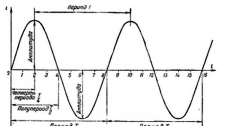
Based on the definition, an alternating current with a certain frequency (in a 50 Hz household electrical network) changes its direction, with a constant value.
Important! Since we know that a polar voltage is needed to power most electrical circuits, in the power supplies of devices, alternating current is replaced by direct current.

This happens in two or three stages:
With the help of a diode assembly, the alternating current is converted into a pulsating one. This is already a straightened graph, however, for the normal functioning of the circuit, this quality of power supply is not enough.

To smooth out ripples, a filter is installed after the bridge. In the simplest case, this is an ordinary polar capacitor. If necessary, increase the quality - a throttle is added.

After conversion and smoothing, it is necessary to ensure a constant value of the operating voltage.
For this, at the third stage, voltage stabilizers are installed.
And yet, the first element of any power supply is a diode bridge.
It can be made both from separate parts and in a mono case.


The first option takes up a lot of space and is more difficult to install.
There are also advantages:
such a design is inexpensive, easier to diagnose, and in the event of failure of one element, only it changes.
The second design is compact, errors in installation are excluded. However, the cost is somewhat higher than that of individual diodes and it is impossible to repair one element, you have to change the entire module.
The principle of operation of the diode bridge
Recall the characteristics and purpose of the diode. If you do not go into technical details - it passes an electric current in one direction, and closes its path in the opposite direction.
This property is already enough to assemble the simplest rectifier on a single diode.
The element is simply included in the circuit in series, and every second current pulse going in the opposite direction is cut off.
This method is called half-wave, and it has many disadvantages:
A very strong ripple, between half-periods there is a pause in the supply of current, equal to the length of half the sinusoid.
As a result of cutting off the lower waves of the sinusoid, the voltage is halved. When accurately measured, the decrease is greater, since there are losses in the diodes as well.

The ability to halve the voltage when it is rectified has found application in housing and communal services.
Residents of multi-apartment entrances, tired of changing constantly burning light bulbs, equip them with diodes.
When switched on in series, the brightness of the glow decreases and the lamp “lives” much longer.
True, strong flicker tires the eyes, and such a lamp is suitable only for emergency lighting.
To reduce losses, a connection of four elements is used.
Full-wave diode bridge, operation scheme:

In whatever direction the alternating current flows at the input contacts, the output of the diode bridge provides a constant polarity at its output contacts.
The ripple frequency of such a connection is exactly twice the frequency of the AC input.
Since the bridge arms cannot pass current in both directions at the same time, stable circuit protection is provided.
Even if the diode bridge in your device is burned out, there will be no short circuit or power surge.
The reliability of the bridge circuit has been proven for decades. Input overvoltage protection is guaranteed by the transformer.
The stabilizer at the output saves from overload. It breaks through the diode bridge only if defective parts are used, or in a car where the circuit is subjected to constant loads.
How does a diode bridge work at minimum voltage?
The voltage drop in the diode bridge is up to 0.7 volts. When using a conventional element base in low-voltage circuits, sometimes the voltage drop is up to 50% of the power supply rating. Such an error is unacceptable..
To ensure the operation of power supplies with a voltage of 1.5 volts to 12 volts, Schottky diodes are used.
With direct current flow, the voltage drop across one crystal is no more than 0.3 volts. We multiply by four elements in the bridge - we get a completely acceptable loss value.
In addition, if the Schottky diode bridge is at the noise level, you will get a value unattainable for silicon p-n diodes.
Another advantage due to the absence of a p-n junction is the ability to operate at a high frequency.
Therefore, rectifiers in excess of high-frequency voltage are made exclusively on diodes of this type.
However, Schottky diodes also have disadvantages.. When exposed to reverse voltage, even for a short time, the element fails.
Checking the diode bridge with a multimeter shows that this very reason has irreversible consequences.
An ordinary germanium or silicon element with a p-n junction is independently restored after a polarity reversal.
Therefore, Schottky diode bridges are used only in low-voltage power supplies and with reverse voltage protection.
What to do if there is a suspicion of a broken bridge?

The rectifier is assembled on a conventional element base, so we will tell you how to check the diode bridge with a multimeter at home.
The illustration shows how the current flows through the bridge. The principle of testing is the same as when testing single diodes.

We look at the reference book, which terminals of the module correspond to a variable input or a polar output - and perform a dial-up.
How to ring a diode bridge without soldering from the circuit?
Since current does not flow in the reverse direction through the diode, incorrect test results indicate a breakdown of the bridge.
There is no need to remove the bridge, the other elements of the power supply do not affect the measurement.
Bottom line: Any of you will be able to independently assemble a diode bridge, and repair it in case of a breakdown. It is enough to have basic skills in electrical engineering.
Watch the video: how to check the diode bridge of your car's generator with a multimeter.
A detailed story on how to check a diode bridge with a multimeter in this video story
car battery
Yaroslav You can collect.
You connect the output from the trance to the Vasily bridge. And from the aluminum "horseshoes" there is a direct current output. But 12 volts is clearly not enough - it should give about 18 volts. Part of the voltage will sit on the diodes, and part on the internal resistance of the trance.
Ilya It depends on what needs to be charged.
-------
Then you can.
Vyacheslav It is necessary above 12v and adjustment of the charging current.
Nikolai Trans must be acc. power, because the charging current should be 1/10 of the battery capacity
Mikhail The voltage is 16 volts, the power of the trance is at least 80 watts. diodes yellow for 10 amps. the simplest is to put a rheostat in the last battery. If you haven’t come across it yourself, ask your friends to help
Gennady 12 volts is not enough. The resistance R1 depends on the voltage at the output of the bridge.
this video describes how you can use diodes from the bridge of a car generator.


I want to connect the Vladimir diode bridge from the Muscovite generator to the transformer, but I don’t know how, tell me. | Topic author: Peter
Diode bridge Andrey can anyone have diagrams, thanks in advance!
Valery There is a three-phase bridge. You can connect, but some of the diodes will not work. Here is the regular diagram:

Peter ? there are normal diode bridges Ivan in the radio shop
Dmitry, knock out 2 and solder, why do you need to blurt out the whole assembly
It is deadly and often lets drivers down on a long journey. ... He will get enough sleep and help you stay awake, distracting you with conversations. ... Cola also helps a little, caffeine is still :)) Personally, I don’t drink coffee, I don’t recognize energy drinks. ..... Sometimes I travel from home to Moscow mainly at night (about 750 km).
How to make a diode bridge to convert AC to DC, single-phase and three-phase diode bridge. Below is a classic diagram of a single-phase diode bridge.
As you can see in the figure, four diodes are connected, an alternating voltage is applied to the input, and the output is already plus and minus. The diode itself is a semiconductor element that can only pass voltage with a certain value through itself. In one direction, the diode can only pass a negative voltage through itself, but a plus cannot, and vice versa in the opposite direction. Below is the diode and its designation in the diagrams. Only minus can pass through the anode, and only plus through the cathode.
 >
>
An alternating voltage is a voltage where, with a certain frequency, it changes plus and minus. For example, the frequency of our 220 volt network is 50 hertz, that is, the voltage polarity changes from minus to plus and back 50 times per second. To rectify the voltage, send a plus to one wire, and a plus to the other, you need two diodes. One is connected by an anode, the second by a cathode, so when a minus appears on the wire, it goes along the first diode, and the second minus does not pass, and when a plus appears on the wire, then, on the contrary, the first plus diode does not pass, and the second passes. Below is a diagram of the principle of operation.
 >
>
For rectification, or rather the distribution of plus and minus in alternating voltage, only two diodes per wire are needed. If there are two wires, then, respectively, two diodes per wire, only four and the connection diagram looks like a rhombus. If there are three wires, then six diodes, two per wire, and that will be a three-phase diode bridge. Below is the connection diagram of a three-phase diode bridge.
 >
>
The diode bridge, as you can see from the pictures, is very simple, this is the simplest device for converting alternating voltage from transformers or generators into direct current. The alternating voltage has a frequency of voltage changes from plus to minus and vice versa, so these ripples are also transmitted after the diode bridge. To smooth out the ripple, if necessary, put a capacitor. The capacitor is placed in parallel, that is, one end to the plus at the output, and the other end to the plus. The capacitor here serves as a miniature battery. It is charging and during the pause between pulses it powers the load by discharging, so the ripples become invisible, and if you connect, for example, an LED, it will not flicker and other electronics will work correctly. Below is a diagram with a capacitor.
 >
>
I also want to note that the voltage passed through the diode decreases slightly, for a Schottky diode it is about 0.3-0.4 volts. Thus, it is possible to lower the voltage with diodes, say 10 series-connected diodes will lower the voltage by 3-4 volts. The diodes heat up precisely because of the voltage drop, let's say a current of 2 amperes flows through the diode, a drop of 0.4 volts, 0.4 * 2 \u003d 0.8 watts, so 0.8 watts of energy is spent on heat. And if 20 amps goes through a powerful diode, then the heating losses will already be 8 watts.
A diode bridge is an elementary electronic circuit that converts AC to DC. It is the most common radio component, without which no rectifier power supply can do.
Structural types of semiconductor bridges
The diode bridge can be assembled from separate semiconductor elements or made as a monolithic assembly. The convenience of the latter is the ease of mounting on a printed circuit board, small overall dimensions. The parameters of the elements in it are carefully selected at the factory, which eliminates their spread and distortion of the temperature regime of operation, however, in the event of failure of one element of such a circuit, the entire assembly must be replaced. If you are not satisfied with ready-made diode assemblies, you can assemble this simple circuit yourself. Installation of elements can be carried out on a printed circuit board, but most often it is made hinged, directly on the transformer. If a high power diode bridge is required, one should not forget that the diodes can get very hot, in which case they are mounted on an aluminum radiator to remove excess heat. Diodes for the bridge must be selected in accordance with the required power of the circuit. The load value can be calculated according to Ohm's law, for this, the maximum current must be multiplied by the maximum voltage. The result should be multiplied by two so that the circuit has a margin of safety. When assembling a diode bridge, it should be remembered that only 70 percent of the rated current flows through each diode.
Principle of operation
An alternating voltage is supplied to the input of the circuit, in the first half-cycle the electric current passes through two diodes, the second pair of diodes is closed. In the second half-cycle, the current passes through the second pair of diodes, and the first is closed. Thus, at the output of the diode bridge, a pulsating voltage is obtained, the frequency of which is twice as high as that of the input. To smooth out the ripple of the output voltage, a capacitor is placed at the output of the bridge.
Application area
Diode bridges are widely used in industrial equipment (power supplies, chargers, motor control circuits, power regulators), in power supplies for household appliances (TVs, refrigerators, vacuum cleaners, computers, power tools, and so on), in lighting devices (fluorescent lamps, in solar panels), in electricity meters.

Diode bridge for welding machine
Such a rectifier must be assembled on the basis of powerful diodes (for example, type B200 with a maximum current of 200 amperes is suitable). They have solid overall dimensions, their body must be placed on an aluminum radiator to remove heat. The case of such diodes is energized, respectively, the radiator too, so the installation must take these features into account. As a result, the design of the welding machine increases in size. However, there are ready-made assemblies on sale, integrated into one case. The dimensions of such a bridge are comparable to a matchbox or one B200 diode without a heatsink. The maximum current is 30-50 amperes, and the price is much lower than the diodes described above.

Diode bridge generator
This is a rectifier unit, consisting of three parallel half-bridges, assembled on six diodes (scheme of the Soviet scientist Larionov A.N.). Such a circuit converts a three-phase alternating voltage into a constant one.
Diode bridge - an electrical circuit designed to convert alternating current to direct pulse. The invention of the circuit in 1897 is attributed to the German physicist Leo Graetz, although English-language sources claim that back in 1895 the diode bridge was created by the “Polish Edison” - electrical engineer Karol Pollak. The scheme became most widespread after the widespread introduction of semiconductor diodes.
The principle of operation of this type of rectifier is based on the property of a semiconductor diode to pass electric current in one direction and not to pass in the other. So, if we connect the plus and minus correctly, current will flow through the device. Swap the plus and minus places - there will be no movement.
Alternating current is different in that during one half-cycle it moves in one direction, and during the second - in the opposite direction. And if you simply include one diode in the circuit, then it will work "usefully" only for one half-cycle. And if you connect the diodes so as to use both half-cycles? Thanks to this idea, bridge rectifiers appeared.
The diode bridge-rectifier circuit is quite simple and can be assembled by hand. It consists of four diodes connected in the form of a square. Two opposite corners are supplied with alternating current from the generator. From the other two opposite corners, a constant is removed. In the first half-cycle, two diodes open, rectifying the half-wave of alternating current. In the second half-cycle, two other diodes open, converting the second half-wave. As a result, the output is a direct current with a pulse frequency twice as high as the frequency of the alternating current.
Advantages and disadvantages of the scheme
- To use a rectified current, the pulse component must be smoothed with a filter-capacitor. The higher the frequency, the better the smoothing process goes. Therefore, doubling the frequency in a bridge circuit is an advantage.
- Full-wave rectification allows you to better use the power of the supply transformer and thereby reduce its size.
Flaws.
- Double the voltage drop compared to a half-wave rectifier.
- The power loss due to heat dissipation is doubled. Low-dropout Schottky diodes are used to reduce losses in high-power, low-voltage circuits.
- If one of the bridge diodes fails, the rectifier will work, but its parameters will differ from normal. This, in turn, can adversely affect the operation of systems powered by the rectifier.
Usage and application
Today, bridges are widely used in all cases where direct current is used - from mobile phones to cars. The industry produces a large number of rectifier devices made according to the bridge circuit. Therefore, choosing the right bridge is not difficult, provided you have a clear understanding of why it is being purchased and what functions it will perform.
Structurally, rectifiers can be made on separate diodes or in the form of a single unit. In the first case, if one of the diodes is damaged, you can replace it. To do this, you need to know how to ring the diode bridge. The test is carried out in the form of a sequential enumeration of all diodes for passing current in the forward and reverse directions. As an indicator, you can use both an ordinary light bulb and a device that measures current strength or resistance.

Despite the availability of factory rectifiers, many are interested in how to make a 12 volt diode bridge on their own. The fact is that 12 volts is the most common voltage for powering many devices, for example, personal computers. And the desire to assemble a rectifier on your own is often quite justified. After all, most inexpensive power supplies that can be purchased do not correspond to the declared parameters for current and power.
Of course, a home-made block is unlikely to look like a factory one, but it will allow you to connect devices in full accordance with the required parameters.
 Despite the fact that the rectifier bridge is not a complex circuit, its assembly requires not only the ability to solder parts, but also correctly calculate their parameters. First of all, you need a power transformer that lowers the voltage to 10 volts. The fact is that the output voltage of the bridge is about 18 percent higher than the input voltage. Therefore, if we apply 12 volts of alternating current to the rectifier, we will get 14-15 volts of direct current, and this can be dangerous for devices designed for 12 volts.
Next, you need to select diodes designed for a double current margin. So, if it is assumed that the rectifier must provide a current of 5 amperes, then the diodes must withstand at least 10 amperes. The capacitor should also have a double margin, but in terms of voltage. And in order to better smooth the rectified current, it must have a large capacitance. Therefore, an electrolytic capacitor is optimal, designed for a voltage of 25 volts, with a capacity of 2000 microfarads. It remains to connect all these parts correctly and check the output parameters using instruments.