How the CHP is working on the corner. Parroid turbine installation with an electric generator
Read also
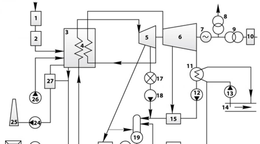
1 - electrical generator; 2 - steam turbine; 3 - control panel; 4 - Deaerator; 5 and 6 - bunkers; 7 - separator; 8 - cyclone; 9 - boiler; 10 - the surface of the heating (heat exchanger); 11 - chimney; 12 - crushing room; 13 - reserve fuel warehouse; 14 - car; 15 - discharge device; 16 - conveyor; 17 - Dymosos; 18 - channel; 19 - ash timer; 20 - fan; 21 - furnace; 22 - mill; 23 - pumping station; 24 - water source; 25 - circulating pump; 26 - a regenerative heater of high pressure; 27 - nutritional pump; 28 - condenser; 29 - installation of chemical water purification; 30 is an increase in transformer; 31 - regenerative low pressure heater; 32 - condensate pump.
The scheme below shows the composition of the main equipment of the thermal electrical station and the relationship of its systems. According to this scheme, you can trace the overall sequence of technological processes of the TPP.

Designations on the TPP scheme:
- Fuel economy;
- fuel preparation;
- intermediate superheater;
- part of high pressure (Chvd or CVD);
- part of low pressure (Cund or CND);
- electrical generator;
- transformer of own needs;
- communication transformer;
- main distribution device;
- condensate pump;
- circulation pump;
- water supply source (for example, river);
- (PND);
- water preparatory installation (VPU);
- consumer thermal energy;
- condensate pump;
- deaerator;
- nutritious pump;
- (PVD);
- slagosol pumping;
- ash card;
- dymosos (DS);
- chimney;
- blowing fans (DV);
- assemander.
Description of the TPP technological scheme:
Summarizing all of the above, we obtain the composition of the thermal power plant:
- fuel economy and fuel preparation system;
- boiler installation: a combination of the boiler itself and auxiliary equipment;
- turbine installation: steam turbine and its auxiliary equipment;
- installation of water treatment and condensate cleaning;
- technical water supply system;
- system of zerochloculcher (for TPPs, working on solid fuel);
- electrical equipment and electrical equipment management system.
Fuel economy Depending on the type of fuel used at the station, turns on the receiving-unloading device, transport mechanisms, fuel warehouses of solid and liquid fuel, devices for pre-tanning fuel preparation (coal crushing plants). The MA-SUCH economy also includes pumps for pumping fuel oil, fuel oil heaters, filters.
Preparation of solid fuel to burning consists of grinding and drying it in a dust-preparatory installation, and the preparation of fuel oil is heated, cleaning from mechanical impurities, sometimes in the processing of special services. Gas fuel is all easier. The preparation of gas fuel is reduced mainly to regulating the gas pressure in front of the boiler burners.
The air is supplied to combustion of fuel fed to the cooler of the boiler by blowing fans (DV). Fuel combustion products - flue gases are sucking with smoke (DS) and are discharged through smoke pipes into the atmosphere. The combination of channels (air ducts and gas ducts) and various elements of the equipment for which air and flue gases are underway, forms a gas-wide path of a thermal power plant (Heat Center). The smokers, chimneys and blowing fans are included in its composition, make up the burst installation. In the combustion zone of fuel included in its composition, non-combustible (mineral) impurities undergo chemical-physical transformations and are separated from the boiler in part in the form of a slag, and a significant part of them are made by smoke gases in the form of small ash particles. To protect the atmospheric air from the emissions of ash in front of the smoke (to prevent their aspaning), zuclear are installed.
The slag and the captured ash are usually removed by the hydraulic way to the alcohol.
When burning fuel oil and gas, the aspores are not installed.
When burning fuel, chemically associated energy turns into thermal. As a result, combustion products are formed, which in the surfaces of the boiler are heat and a pair of water and the resulting pair.
A combination of equipment, individual elements, pipelines, which move water and steam, form a steam path of the station.
In the boiler, water is heated to the saturation temperature, evaporates, and the rich steam generated from the boiling waterproof. From the boiler overheated pairs is heading through the pipelines into the turbine, where its thermal energy turns into a mechanical transmitted to the turbine shaft. The pairs spent in the turbine enters the capacitor, gives the heat of cooling water and condenses.
On modern TPPs and CHP with aggregates of a single power of 200 MW and above, intermediate overheating of steam is used. In this case, the turbine has two parts: part of the high and part of the low pressure. The steam turbine, spent in terms of high pressure, is sent to an intermediate superheater, where heat is additionally supplied to it. Next, the pairs return to the turbine (into a portion of low pressure) and it enters the condenser. Intermediate steam overheating increases the efficiency of the turbine unit and increases the reliability of its operation.
From the condenser, condensate is pumped up by a condensation pump and, passing through low pressure heaters (PND), enters the deaerator. Here it is heated by steam to saturation temperature, and oxygen and carbon dioxide is released from it and removed to the atmosphere of oxygen and carbon dioxide to prevent corrosion of equipment. Deaerated water, called nutritious, is supplied through high pressure heaters (PVD) to the boiler.
Condensate in PND and deaerator, as well as nutrient water in PVD, is heated by a ferry, selected from the turbine. This method of heating means return (regeneration) of heat into the cycle and is called regenerative heating. Due to it, the admission of steam into the capacitor decreases, and therefore the amount of heat transmitted by cooling water, which leads to an increase in the efficiency of the steam turbine unit.
The combination of elements providing condensers with cooling water is called a system of technical water supply. It includes: water supply source (river, reservoir, tower cooler - cooling tower), circulating pump, applying and discharged waterways. In the condenser of cooled water, approximately 55% of the heat of the steam entering the turbine is transmitted; This part of the heat is not used to generate electricity and disappears useless.
These losses are significantly reduced, if partially spent partially spent steam and heat from the turbine and use it for the technological needs of industrial enterprises or heating water to heating and hot water supply. Thus, the station becomes a thermal electrofentral (CHP), which provides combined production of electrical and thermal energy. Special turbines with pair selection are installed on the CHP - the so-called heat reference. Condensate pair, given to the thermal consumer, returns to the CHP pump of reverse condensate.
The TPPs exist internal losses of steam and condensate, due to the incomplete tightness of the steam room, as well as the non-returnable consumption of steam and condensate for the technical needs of the station. They constitute approximately 1 - 1.5% of the total consumption of steam per turbine.
There may be external losses of steam and condensate associated with the release of warmth to industrial consumers. On average, they make up 35 - 50%. The internal and external losses of steam and condensate are replenished previously treated in the water-producing installation.
Thus, the nutrient water of the boilers is a mixture of turbine condensate and added water.
The electrical economy of the station includes an electric generator, a communications transformer, a main distribution device, a power supply system of its own power plant mechanisms through a transformer of own needs.
The control system collects and process information on the process of the technological process and the condition of the equipment, automatic and remote control of the mechanisms and regulation of the main processes, automatic equipment protection.
Thermal power plants can be with steam and gas turbines, with internal combustion engines. The most common thermal stations with steam turbines, which in turn are divided into: condensation (CAC) - all pairs in which, with the exception of small selections for heating the nutritious water, is used to rotate the turbine, generating electrical energy; heat power plants - Thermal-power center (CHP), which are the power supply of electric and thermal energy consumers and are located in the area of \u200b\u200btheir consumption.
Condensation power plants
Condensation power plants are often called state district electric stations (GRES). The CAP is mainly located near the areas of fuel extraction or water bodies used for cooling and condensation of a steam spent in turbines.
Characteristic features of condensation electric stations
- for the most part, significant remoteness from the consumers of electrical energy, which causes the need to transmit electricity mainly on stresses of 110-750 kV;
- the block principle of building a station, providing significant technical and economic advantages, which consist in increasing the reliability of work and relief, in reducing the volume of construction and installation work.
- Mechanisms and installations that ensure the normal functioning of the station make up its system.
The CPP can work on solid (coal, peat), liquid (fuel oil, oil) fuel or gas.
The fuel feed and the preparation of solid fuels is to transport it from the warehouses into the fuel-receiving system. In this system, fuel is brought to a dust-like state in order to further enjoy it to the burners of the boiler firebox. To maintain the combustion process with a special fan in the furnace, air heated by waste gases are injected, which are saturated from the firing of the smoke.
Liquid fuel is supplied to the burners directly from the warehouse in the heated form by special pumps.

The preparation of gas fuel consists mainly in regulating gas pressure before burning. Gas from the field or repository is transported by gas pipeline to the gas distribution point (GPA) station. The gas distribution and control of its parameters is carried out on the hydraulic system.
Processes in a steam circuit
The main steam outline performs the following processes:
- The burning of fuel in the furnace is accompanied by heat release, which heats the water flowing into the pipes of the boiler.
- Water turns into pairs with a pressure of 13 ... 25 MPa at a temperature of 540..560 ° C.
- Couples obtained in the boiler are served in the turbine where it makes mechanical work - the turbine shaft rotates. As a result, the generator rotor is also rotated, which is in common with the turbine shaft.
- The steam spent in the turbine with a pressure of 0.003 ... 0.005 MPa at a temperature of 120 ... 140 ° C is a condenser, which turns into water, which is pumped into a deaerator.
- In Deaaerator, dissolved gases occurs, and first of all the oxygen, dangerous due to its corrosive activity. The circulation water system provides cooling of steam in a condenser with water from an external source (reservoir, river, artesian well). Chilled water having a temperature at the output from the condenser not exceeding 25 ... 36 ° C is reset to the water supply system.
Interesting video about the work of CHP can be viewed below:
To compensate for the loss of steam into the main steaming system, the pump is supplied to the pump, pre-past chemical cleaning.
It should be noted that for normal operation of steaming installations, especially with over critical steam parameters, the quality of water supplied to the boiler is important, so the turbine condensate is passed through the desalting filter system. The water treatment system is designed to clean the feed and condensate water, the removal of dissolved gases from it.
At stations using solid fuel, combustion products in the form of slag and ashes are removed from the firebox of boilers with a special slag and zeroing system equipped with special pumps.
When burning gas and fuel oil such a system is required.
The CAC has significant energy losses. Especially large heat loss in the condenser (up to 40..50% of the total heat released in the furnace), as well as with outgoing gases (up to 10%). The efficiency coefficient of modern IES with high pressure parameters and pair temperature reaches 42%.
The electrical part of the CPP represents a set of main electrical equipment (generators,) and electrical equipment of their own needs, including collectible tires, switching and other equipment with all compounds fulfilled between them.
Station generators are connected to blocks with promoters without any devices between them.
In this regard, the CPP does not build a distribution device of the generator voltage.
Distributing devices for 110-750 kV depending on the number of connections, voltage transmitted power and the required level of reliability are performed according to typical circuits of electrical connections. Transverse links between blocks take place only in the distribution devices of the highest or in the power system, as well as fuel, water and pair.
In this regard, each power unit can be viewed as a separate autonomous station.
To ensure the electricity of its own needs the station, an exile from the generators of each block are performed. To power the powerful electric motors (200 kW and more), the generator voltage is used, to power the engines of lower power and lighting installations - 380/220 B. Electric circuits of the station's own needs can be different.
Another interesting video about the work of the CHP from the inside:
Heat and power center
The heat-power center, being sources of the combined generation of electrical and thermal energy, are significantly larger than the KES, (up to 75%). This is explained by topics. that part of the steam spent in the turbines is used for the needs of industrial production (technology), heating, hot water supply.
This pair or directly arrives for production and household needs or is partially used to preheat water in special boilers (heaters), of which water through the heat network is sent to consumers of thermal energy.
The main difference in energy production technology on in comparison with the COP consists in the specifics of the steam conduit. Providing intermediate selection of a pair of turbine, as well as in the method of issuing energy, in accordance with which the main part is distributed on the generator voltage through the generator switchgear (GRU).
Communication with other power grid stations is performed on high voltage through increasing transformers. When repairing or disabling one generator, the missing power can be transmitted from the power system through the same transformers.
To increase the reliability of the CHP, it is envisaged to partitioning the tires.
Thus, when the tire accidents and the subsequent repair of one of the sections of the second section remains in operation and provides power to consumers for the remaining lines.
According to such schemes, industrial with generators up to 60 MW, designed to power the local load within a radius of 10 km.
On large modern, generators with a capacity of up to 250 MW with a total power of a 500-2500 MW station.
Such are constructed beyond the features of the city and electricity is transmitted at a voltage of 35-220 kV, GRU is not provided, all generators are connected to blocks with rising transformers. If it is necessary to power the small local load near the block, an exile from the blocks between the generator and the transformer are provided. The combined stations schemes are also possible, under which there are GRU and several generators are connected by block diagrams.
The modern world requires a huge amount of energy (electrical and thermal), which is produced on power plants of various types.
The person learned how to produce energy from several sources (hydrocarbon fuel, nuclear resources, falling water, wind, etc.) However, to this day, thermal and nuclear power plants remain in demand and effective, which will be discussed.
What is NPP?
The nuclear power plant (NPP) is an object on which the reaction of the decay of nuclear fuel is used for the production of energy.
Attempts to use controlled (i.e. controlled, predicted) nuclear reaction for electricity generation were taken by Soviet and American scientists at the same time - in the 40s of the last century. In the 50s, the "peaceful atom" became a reality, and in many countries of the world began to build a nuclear power plant.
The central node of any nuclear power plant is a nuclear installation in which the reaction occurs. When decaying radioactive substances, a huge amount of heat is allocated. The heat energy is used to heat the coolant (as a rule, water), which, in turn, heats the water of the second circuit until it is transition to steam. Hot steam rotates turbines, due to which electricity is being generated.
The world does not subscribe to disputes about the feasibility of using atomic energy to generate electricity. NPP supporters speak of their high productivity, the safety of the recent generation reactors, as well as that such power plants do not pollute the environment. Opponents argue that NPPs are potentially extremely dangerous, and their exploitation and, especially, the utilization of spent fuel is associated with huge expenditures.
What is TPP?
The most traditional and distributed in the world of power plants are TPP. Thermal power plants (this abbreviation is so decrypted) produce electricity by burning hydrocarbon fuel - gas, coal, fuel oil. 
The scheme of operation of the TPP looks like this: when combustion of fuel is formed a large number of thermal energy, with which water heats up. Water turns into overheated pairs, which is served in the turbogenerator. Rounding, the turbine leads the details of the electric generator, the electrical energy is formed.
On some CHP phase of heat transfer heat carrier (water) is absent. They use gas turbine installations in which the turbines rotate the gases obtained directly when fuel combustion.
The essential advantage of the TPP is the availability and relative cheapness of fuel. However, there are thermal stations and disadvantages. This is primarily a threat to the environment. When burning fuel into the atmosphere, a large amount of harmful substances are ejected. To make TPPs safer, a number of methods are applied, including: fuel enrichment, installation of special filters, delaying harmful compounds, the use of flue gas recycling, etc.
What is CHP?
The name of this object itself resembles the previous, and in fact, the CHP, as well as thermal power plants convert the thermal energy of the fuel of the fuel. But in addition to the electricity of the heat and power plant (the CHP is so deciphered) supply heat to consumers. The CHP is particularly relevant in cold climatic zones, where you need to provide residential buildings and production buildings with warmth. That is why CHP is so many in Russia, where the central heating and water supply of cities traditionally is used.
On the principle of operation, the CHP refers to condensation power plants, but in contrast to them, on heat and power plants, part of the produced thermal energy goes to the production of electricity, and the other part is to heat the coolant, which comes to the consumer. 
CHP is more effective compared to conventional TPPs, since it allows the use of the resulting energy to the maximum. After all, after rotating the electric generator, the steam remains hot, and this energy can be used for heating.
In addition to thermal, there are atomic CHPs, which in the future should play a leading role in the electro- and heat supply of the northern cities.
May 29th, 2013
The original is taken by W. zao_jbi. In the post what the CHP is and how it works.
One day, when we went into the glorious city of Cheboksary, from the east direction, my spouse drew attention to two huge towers, standing along the highway. "And what is it?" She asked. Since I absolutely did not want to show my ignorance my wife, I fought a little in my memory and issued a victorious: "This is a cooling towers, you don't know what?". She was a little embarrassed: "And why are they needed?" "Well, something there is cooling, it seems." "And what?". Then I was embarrassed, because I did not know at all how to get out on.
Maybe this question remained forever in memory unanswered, but miracles happen. A few months after this incident, I see the post in my Frandlent z_alexey About a set of bloggers who want to visit Cheboksary CHP-2, the one that we have seen from the road. You have to dramatically change all your plans, misinterpret such a chance will be unforgivable!
So what is CHP?
This is the heart of the CHP, and here is the main action. Gas entering the boiler burns, highlighting a crazy amount of energy. Clean water is served here. After heating, it turns into steam, more precisely in overheated pairs having a temperature at a yield of 560 degrees, and the pressure 140 atmospheres. We also call it "pure couples" because it is formed from the prepared water.
In addition to steam, we still have exhaust. At maximum power, all five boilers consume almost 60 cubic meters of natural gas per second! To bring the combustion products, you need a nonsense "smoke" pipe. And this is also available.
The pipe is seen from almost any city district, given the height of 250 meters. I suspect that this is the highest structure in Cheboksary.
Nearby is a pipe just smaller. Reserve again.
If the CHP operates on the corner, additional exhaust cleaning is necessary. But in our case it is not required, since natural gas is used as fuel.
In the second separation of the Cotturbinarian workshop, plants producing electricity are located.
In the Machine Hall of Cheboksary CHP-2, there are four pieces, a total of 460 MW (Megawatt). It is here that overheated couples from the boiler room are served. It, under huge pressure, is heading for the turbine blades, forcing the thirty-tunic rotor rotate, at a speed of 3000 revolutions per minute.
The installation consists of two parts: the actual turbine itself, and the generator generating electricity.
But what does the turbine rotor look like.
Everywhere sensors and pressure gauges.
And turbines, and boilers, in case of an emergency, you can stop instantly. For this, there are special valves that can overlap the supply of steam or fuel for some fractions of a second.
I wonder if there is such a thing as an industrial landscape, or an industrial portrait? There is a beauty here.
There is a terrible noise in the room, and to hear the neighbor to have a lot of rumor. Besides very hot. I want to remove the helmet and undress to the T-shirt, but it is impossible to do this. Safety, short-sleeved clothing for CHP is prohibited, too many hot pipes.
The bulk of the workshop is empty, people here appear once every two hours during bypass. And the management of the equipment is carried out with greeshi (group boards of control boilers and turbines).
This is how duty work looks like.
Around hundreds of buttons.
And dozens of sensors.
There are mechanical, there is electronic.
This is our excursion, and people work.
Total, after the bottom-binding shop, we have electricity at the exit and partially cooled and lost part of the pressure of steam. With electricity, it seems to be easier. At the exit from different generators, the voltage can be from 10 to 18 kV (kilovolt). Using block transformers, it increases to 110 kV, and then electricity can be transmitted over long distances using LPP (power lines).
The remaining "clean couple" to let go side unprofitable. Since it is formed from "clean water", the production of which is a rather complicated and costly process, it is advisable to cool and return it back into the boiler. So on a closed circle. But with its help, and with the help of heat exchangers you can heat water or produce secondary steam, which calmly sell to third-party consumers.
In general, it is in this way, we get warm and electricity to your homes, having familiar comfort and comfort.
Oh yes. And why do you still need cooling towers?
It turns out everything is very simple. To cool, the remaining "pure pairs", in front of the new supply to the boiler, uses all the same heat exchangers. It is cooled with the help of technical water, on the CHP-2 it takes it straight from the Volga. It does not require any special training and can also be reused. After passing the heat exchanger, the technical water heats up and goes to the cooling towers. There it flows a thin film down or falls down in the form of droplets and is cooled due to the oncoming air flow created by fans. And in ejection cooling glands, water is sprayed with special nozzles. In any case, the main cooling occurs due to evaporation of a small part of the water. With the cooling cycle, the cooled water goes through a special channel, after which, using a pumping station is sent to reuse.
In a word, cooling the cooling towers to cool water, which cools the steam working in the boiler system - turbine.
All the work of the CHP is controlled from the main control panel.
Here is constantly on duty.
All events are logged in.
I do not eat bread, let me take a picture buttons and sensors ...
On this, almost all. At the end there are few photographs of the station.
This old, no longer working trumpet. Most likely it will be demolished soon.
The company has a lot of agitation.
Here are proud of their employees.
And their achievements.
It seems that it is not in vain ...
It remains to add that as in the anecdote - "I do not know who these bloggers, but the guide of the branch of the branch in Mari El and Chuvashia OJSC TGK-5, KES Holding - Dobrov S.V.
Together with the director of the station S.D. Stolyarov.
Without exaggeration - real professionals of their business.
And of course, thanks to Irina Romanova, which represents the press service of the company, for the perfectly organized tour.
Heat electrofentral (CHP)
The greatest distribution of CHP received in the USSR. The first heat pipes were laid from the power plants of Leningrad and Moscow (1924, 1928). From the 30s. Design and construction of CHP capacity of 100-200 MW. By the end of 1940, the power of all operating CHP reached 2 GW annual release of heat - 10 8 GJ And the length of thermal networks (see the thermal network) - 650 km. In the mid-70s. The total electric power of the CHP is about 60 GW (with the total power of power plants of thermal power plane 220 and thermal power plants of thermal electrical electrical components 180 GW). The annual electricity generation at the CHP reaches 330 billion. kvch, Heat vacation - 4.10 9 GJ; Power of individual new CHP - 1.5-1.6 GWwith the watch of heat leave to (1.6-2.0) .10 4 GJ; Specific electricity generation upon vacation 1 GJ. Heat - 150-160 kWh. Specific consumption of conditional fuel for production 1 kWh. Electricity averages 290 g. (whereas on GRES - 370 g.);
The smallest average annual specific consumption of conditional fuel at the CHP about 200 g / kvch (on the best GRES - about 300 g / kvch). Such a reduced (compared to GRES) The specific fuel consumption is due to the combined production of the energy of two types using the heat of the spent steam. In the USSR, CHES gives savings to 25 million. t. Conditional fuel per year (heat-power center 11% of the entire fuel coming into electricity production). CHP - the main production link in the system of centralized heat supply. The construction of the CHP is one of the main directions for the development of the energy economy in the USSR and other socialist countries. In capitalist countries, the CHP has limited distribution (mainly industrial CHP). LIT: Sokolov E. Ya., Heat Protection and thermal networks, M., 1975; Ryzhkin V. Ya., Heat electric stations, M., 1976. V. Ya. Ryzhkin.
Great Soviet Encyclopedia. - M.: Soviet Encyclopedia. 1969-1978 .
Synonyms:Watch what is "heat-power center" in other dictionaries:
- (CHP), a steam turbine thermal power plant, generating and released by consumers at the same time 2 types of energy: electrical and thermal (in the form of hot water, steam). In Russia, the power of individual CHP reaches 1.5 1.6 GW at the watch ... ... Modern encyclopedia
- (CHP thermal power plant), a thermal power plant generating not only electrical energy, but also heat released by consumers in the form of steam and hot water ... Big Encyclopedic Dictionary
Heat-power center, and, wives. Thermal power plant generating electricity and heat (hot water, steam) (CHP). Explanatory dictionary of Ozhegov. S.I. Ozhegov, N.Yu. Swedov. 1949 1992 ... Explanatory Dictionary of Ozhegova Large Polytechnic Encyclopedia
CHP 26 (South CHP) in Moscow ... Wikipedia