Heating stations. Combined Heat and Power Plant (CHP)
Electrical energy has long entered our life. Even the Greek philosopher Thales in the 7th century BC discovered that amber, worn against wool, begins to attract objects. But for a long time no one paid attention to this fact. Only in 1600 the term "Electricity" first appeared, and in 1650 Otto von Guericke created an electrostatic machine in the form of a sulfur ball mounted on a metal rod, which allowed observing not only the effect of attraction, but also the effect of repulsion. It was the first simplest electrostatic machine.
Many years have passed since then, but even today, in a world filled with terabytes of information, when you can find out everything that interests you, for many it remains a mystery how electricity is produced, how it is delivered to our home, office, enterprise ...
We will consider these processes in several parts.
Part I. Generation of electrical energy.
Where does electrical energy come from? This energy appears from other types of energy - thermal, mechanical, nuclear, chemical and many others. On an industrial scale, electrical energy is obtained at power plants. Let's consider only the most common types of power plants.
1) Thermal power plants. Today, they can be combined with one term - GRES (State District Power Plant). Of course, today this term has lost its original meaning, but it did not disappear into eternity, but remained with us.
Thermal power plants are divided into several subtypes:
A) Condensing power plant (CES) is a thermal power plant that produces only electrical energy; this type of power plant owes its name to the peculiarities of the principle of operation.
Principle of operation: Air and fuel (gaseous, liquid or solid) are supplied to the boiler by means of pumps. It turns out a fuel-air mixture that burns in the boiler furnace, releasing a huge amount of heat. In this case, the water flows through the pipe system, which is located inside the boiler. The released heat is transferred to this water, while its temperature rises and is brought to a boil. The steam that was obtained in the boiler goes back to the boiler to overheat it above the boiling point of water (at a given pressure), then through steam pipelines it enters the steam turbine, in which the steam does work. At the same time, it expands, its temperature and pressure decrease. Thus, the potential energy of the steam is transferred to the turbine, which means it turns into kinetic energy. The turbine, in turn, drives the rotor of a three-phase alternator, which is on the same shaft with the turbine and produces energy.
Let's take a closer look at some of the IES elements.
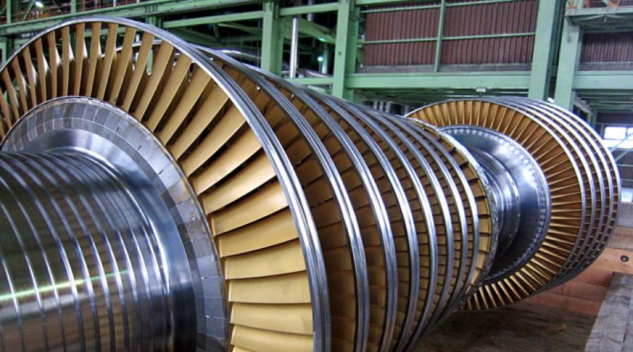
Steam turbine.

The flow of water vapor enters through the guide vanes onto the curved blades fixed around the circumference of the rotor, and, acting on them, drives the rotor into rotation. As you can see, there are gaps between the rows of shoulder blades. They are because this rotor is removed from the housing. Rows of blades are also built into the body, but they are stationary and serve to create the desired angle of incidence of steam on the moving blades.
Condensing steam turbines are used to convert as much of the heat of the steam as possible into mechanical work. They work with the discharge (exhaust) of the exhaust steam into a condenser in which a vacuum is maintained.
A turbine and a generator that are on the same shaft are called a turbine generator. Three-phase alternator (synchronous machine).

It consists of:


Which raises the voltage to the standard value (35-110-220-330-500-750 kV). In this case, the current decreases significantly (for example, when the voltage increases by 2 times, the current decreases by 4 times), which makes it possible to transmit power over long distances. It should be noted that when we talk about voltage class, we mean line-to-line (phase-to-phase) voltage.
The active power generated by the generator is regulated by changing the amount of energy carrier, while the current in the rotor winding changes. To increase the output active power, it is necessary to increase the steam supply to the turbine, while the current in the rotor winding will increase. It should not be forgotten that the generator is synchronous, which means that its frequency is always equal to the frequency of the current in the power system, and changes in the parameters of the energy carrier will not affect the frequency of its rotation.
In addition, the generator also generates reactive power. It can be used to regulate the output voltage within small limits (i.e., it is not the main means of regulating the voltage in the power system). It works this way. When the rotor winding is overexcited, i.e. when the voltage on the rotor exceeds the nominal value, the “surplus” of reactive power is supplied to the power system, and when the rotor winding is under-excited, the reactive power is consumed by the generator.
Thus, in alternating current we are talking about the total power (measured in volt-amperes - VA), which is equal to the square root of the sum of active (measured in watts - W) and reactive (measured in volt-amperes reactive - VAR) powers.
The water in the reservoir serves to remove heat from the condenser. However, spray pools are often used for these purposes.
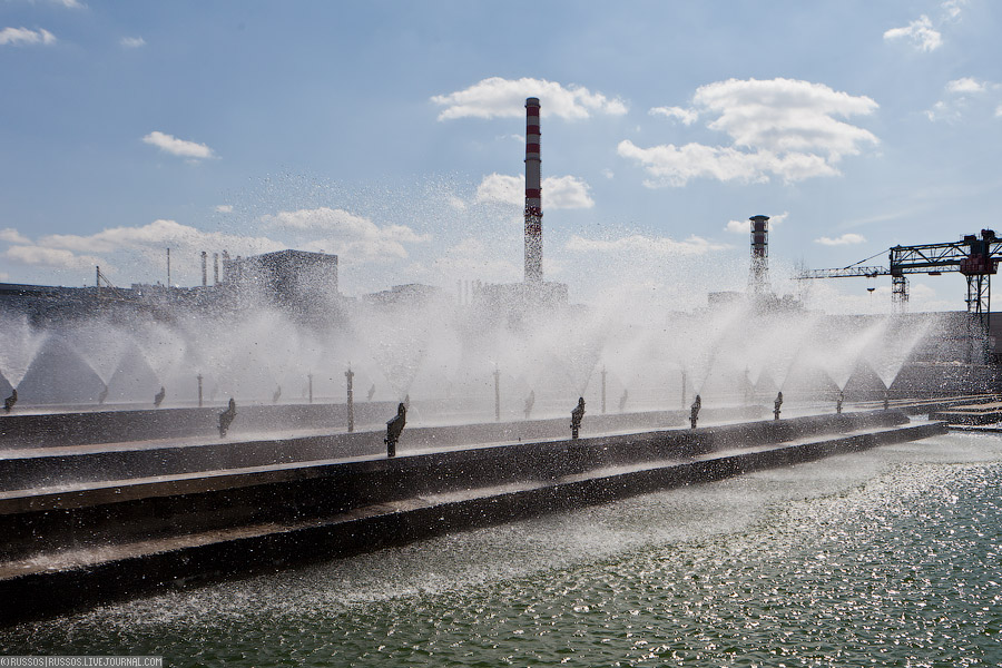
or cooling towers. Cooling towers are tower Fig. 8

or fan Fig. 9

Cooling towers are arranged in almost the same way, with the only difference that the water flows down the radiators, transfers heat to them, and they are already cooled by the forced air. In this case, part of the water evaporates and is carried away into the atmosphere.
The efficiency of such a power plant does not exceed 30%.
B) Gas turbine power plant.
At a gas turbine power plant, the turbine generator is not driven by steam, but directly by gases obtained from the combustion of fuel. In this case, only natural gas can be used, otherwise the turbine will quickly come out of standing due to its contamination with combustion products. Efficiency at maximum load 25-33%
Much higher efficiency (up to 60%) can be obtained by combining steam and gas cycles. Such installations are called combined cycle plants. Instead of a conventional boiler, a waste heat boiler is installed in them, which does not have its own burners. It receives heat from the exhaust of a gas turbine. Currently, CCGTs are actively being introduced into our life, but so far there are not many of them in Russia.
V) Combined heat and power plants (for a long time they have become an integral part of large cities). Fig. 11

The CHP is designed as a condensing power plant (CES). The peculiarity of this type of power plant is that it can simultaneously generate both thermal and electrical energy. Depending on the type of steam turbine, there are various methods of steam extraction, which allow the extraction of steam from it with different parameters. In this case, part of the steam or all of the steam (depending on the type of turbine) enters the network heater, gives it heat and condenses there. Heating turbines allow you to regulate the amount of steam for thermal or industrial needs, which allows the CHPP to operate in several modes according to the load:
thermal - the generation of electrical energy is entirely dependent on the production of steam for industrial or district heating needs.
electrical - electrical load is independent of heat. In addition, CHP plants can operate in a fully condensing mode. This may be required, for example, when there is a sharp shortage of active power in summer. Such a regime is disadvantageous for CHP plants, since efficiency is significantly reduced.
Simultaneous production of electricity and heat (cogeneration) is a profitable process in which the efficiency of the plant is significantly increased. So, for example, the calculated efficiency of the IES is a maximum of 30%, while that of the CHP is about 80%. Plus, cogeneration can reduce idle thermal emissions, which has a positive effect on the ecology of the area where the CHP is located (compared to if there was a CES of the same capacity).
Let's take a closer look at the steam turbine.
Cogeneration steam turbines include turbines with:
Back pressure;
Regulated steam extraction;
By selection and back pressure.
Backpressure turbines work with steam exhaust not into the condenser, as in the KES, but into the network heater, that is, all the steam that went through the turbine goes to heating needs. The design of such turbines has a significant drawback: the electrical load schedule completely depends on the heat load schedule, that is, such devices cannot take part in the operational regulation of the current frequency in the power system.
In turbines with controlled extraction of steam, it is extracted in the required amount in intermediate stages, while selecting such stages for extraction of steam, which are suitable in this case. This type of turbine is independent of the heat load and the regulation of the output active power can be adjusted within a wide range than in a CHP with back pressure.
Extraction and back pressure turbines combine the functions of the first two types of turbines.
Heating turbines of CHP plants are not always able to change the heat load in a short period of time. To cover load peaks, and sometimes to increase electrical power by transferring turbines to condensing mode, peak hot water boilers are installed at CHPPs.
2) Nuclear power plants.
At the moment, there are 3 types of reactor plants in Russia. The general principle of their operation is roughly similar to the work of IES (in the old days, NPPs were called GRES). The fundamental difference lies only in the fact that thermal energy is obtained not in fossil fuel boilers, but in nuclear reactors.
Consider the two most common types of reactors in Russia.
1) RBMK reactor.

A distinctive feature of this reactor is that steam for rotating the turbine is obtained directly in the reactor core.
RBMK core. Fig. 13

consists of vertical graphite columns, in which there are longitudinal holes, with inserted pipes made of zirconium alloy and stainless steel. Graphite acts as a neutron moderator. All channels are divided into fuel and CPS channels (control and protection system). They have different cooling circuits. A cassette (fuel assembly - fuel assembly) with rods (fuel rod - fuel element) is inserted into the fuel channels, inside which there are uranium pellets in a sealed shell. It is clear that it is from them that heat energy is obtained, which is transferred to the coolant continuously circulating from the bottom up under high pressure - ordinary, but very well purified from impurities water.

Water passing through the fuel channels partially evaporates, the steam-water mixture flows from all separate fuel channels into 2 drum-separators, where the separation (separation) of steam from water takes place. Water again goes into the reactor with the help of circulation pumps (only 4 per loop), and steam goes through steam lines to 2 turbines. Then the steam is condensed in a condenser, turns into water, which goes back to the reactor.
The thermal power of the reactor is controlled only with the help of boron neutron absorber rods, which move in the CPS channels. The water cooling these channels goes from top to bottom.
As you can see, I have never said anything about the reactor vessel. The fact is that the RBMK does not actually have a hull. The active zone about which I just told you is placed in a concrete shaft, from above it is closed with a cover weighing 2000 tons.

The figure shows the upper biological shield of the reactor. But do not expect that by lifting one of the blocks, it will be possible to see the yellow-green throat of the active zone, no. The lid itself is located much lower, and above it, in the space up to the upper biological protection, there is a gap for the communications of the channels and the completely removed absorber rods.
Space is left between the graphite columns for thermal expansion of the graphite. A mixture of nitrogen and helium gases circulates in this space. Its composition is used to judge the tightness of the fuel channels. The RBMK core is designed for a rupture of no more than 5 channels; if more depressurization occurs, the reactor lid will break off and the remaining channels will open. Such a development of events will cause a repetition of the Chernobyl tragedy (here I mean not the man-made disaster itself, but its consequences).
Consider the advantages of RBMK:
—Thanks to channel-by-channel regulation of thermal power, it is possible to change fuel assemblies without shutting down the reactor. There are usually several assemblies being changed every day.
—Low pressure in the MCC (multiple forced circulation circuit), which contributes to a softer course of accidents associated with its depressurization.
- Lack of complicated manufacturing of the reactor vessel.
Consider the cons of RBMK:
—In the course of operation, numerous miscalculations were discovered in the geometry of the core, which cannot be completely eliminated at the operating power units of the 1st and 2nd generations (Leningrad, Kursk, Chernobyl, Smolensk). RBMK power units of the 3rd generation (it is one - at power unit 3 of the Smolensk NPP) is devoid of these drawbacks.
- The reactor is single-loop. That is, the turbines are driven by steam produced directly in the reactor. This means that it contains radioactive components. If the turbine is depressurized (and this was the case at the Chernobyl nuclear power plant in 1993), its repair will be greatly complicated, and perhaps even impossible.
- The service life of the reactor is determined by the service life of the graphite (30-40 years). Then comes its degradation, which manifests itself in its swelling. This process is already causing serious concern at the oldest RBMK power unit, Leningrad-1, built in 1973 (it is already 39 years old). The most likely way out of the situation is damping the n-th number of channels to reduce the thermal expansion of graphite.
—The graphite retarder is a combustible material.
- Due to the huge number of valves, the reactor is difficult to control.
- On the 1st and 2nd generations, there is an instability when working at low capacities.
In general, we can say that the RBMK is a good reactor for its time. At present, it has been decided not to build power units with this type of reactors.
2) VVER reactor.

The RBMK is now being replaced by VVER. It has significant advantages over RBMK.
The core is completely located in a very robust building, which is manufactured at the plant and transported by rail and then by road to the power unit under construction in a completely finished form. The retarder is pure pressurized water. The reactor consists of 2 circuits: water in the primary circuit under high pressure cools the fuel assemblies, transferring heat to the 2nd circuit using a steam generator (performs the function of a heat exchanger between 2 isolated circuits). In it, the water of the secondary circuit boils, turns into steam and goes to the turbine. In the first circuit, water does not boil, since it is under very high pressure. The waste steam is condensed in the condenser and goes back to the steam generator. The double-circuit circuit has significant advantages over the single-circuit:
The steam going to the turbine is not radioactive.
The power of the reactor can be controlled not only by the absorber rods, but also by the boric acid solution, which makes the reactor more stable.
The elements of the primary circuit are located very close to each other, so they can be placed in a common protective shell. In the event of ruptures in the primary circuit, radioactive elements will enter the containment and will not be released into the environment. In addition, the containment protects the reactor from external influences (for example, from the fall of a small aircraft or an explosion outside the station perimeter).
The reactor is not difficult to operate.
There are also disadvantages:
- Unlike RBMK, the fuel cannot be changed while the reactor is running. it is located in a common building, and not in separate channels, as in RBMK. The fuel reload time usually coincides with the current repair time, which reduces the effect of this factor on the ICUF (coefficient of installed capacity used).
—The primary circuit is under high pressure, which could potentially cause a larger scale of a breakdown accident than the RBMK.
—The reactor body is very difficult to transport from the manufacturing plant to the NPP construction site.
Well, we examined the work of thermal power plants, now we will consider the work

The principle of operation of a hydroelectric power station is quite simple. The chain of hydraulic structures provides the necessary pressure of water entering the blades of the hydraulic turbine, which drives the generators that generate electricity.
The required water pressure is formed by the construction of a dam, and as a consequence of the concentration of the river in a certain place, or by derivation - by the natural flow of water. In some cases, to obtain the required water pressure, both the dam and the derivation are used together. Hydroelectric power plants have a very high maneuverability of the generated power, as well as a low cost of the generated electricity. This feature of the hydroelectric power station led to the creation of another type of power plant - a pumped storage power plant. Such stations are capable of accumulating the generated electricity and putting it into operation at times of peak loads. The principle of operation of such power plants is as follows: at certain times (usually at night), hydroelectric units of the PSPP work as pumps, consuming electrical energy from the power system, and pump water into specially equipped upper basins. When a demand arises (in load peaks), water from them enters the pressure pipeline and drives the turbine. Pumped storage power plants perform an extremely important function in the power system (frequency regulation), but they are not widely used in our country, because as a result, they consume more power than they give out. That is, a station of this type is unprofitable for the owner. For example, at the Zagorskaya PSPP, the capacity of hydrogenerators in the generator mode is 1200 MW, and in the pumping mode - 1320 MW. However, this type of plant is best suited for rapidly increasing or decreasing the generated power, therefore it is advantageous to build them near, for example, nuclear power plants, since the latter operate in a basic mode.
We have examined exactly how electrical energy is produced. It's time to ask yourself a serious question: "And what type of stations best meets all modern requirements for reliability, environmental friendliness, and besides that, it will also have a low cost of energy?" Everyone will answer this question differently. Here is my list of the "best of the best."
1) Natural gas CHP. The efficiency of such stations is very high, and the cost of fuel is also high, but natural gas is one of the "cleanest" types of fuel, and this is very important for the ecology of the city, within which CHP plants are usually located.
2) HPP and PSP. The advantages over thermal power plants are obvious, since this type of power plant does not pollute the atmosphere and produces the “cheapest” energy, which, in addition to everything, is a renewable resource.
3) CCGT unit on natural gas. The highest efficiency among thermal power plants, as well as a small amount of fuel consumed, will partially solve the problem of thermal pollution of the biosphere and limited reserves of fossil fuels.
4) NPP. In normal operation, a nuclear power plant emits into the environment 3-5 times less radioactive substances than a thermal power plant of the same capacity, therefore, partial replacement of thermal power plants with nuclear ones is quite justified.
5) State District Power Plant. Currently, such stations use natural gas as a fuel. This is absolutely senseless, since with the same success in the furnaces of the state district power station, it is possible to utilize associated petroleum gas (APG) or to burn coal, the reserves of which are enormous in comparison with the reserves of natural gas.
This concludes the first part of the article.
Material prepared by:
student of ES-11b group of South-Western State University Agibalov Sergey.
Combined heat and power plant (CHP)
The most widespread thermal power plants are in the USSR. The first heat pipelines were laid from the power plants of Leningrad and Moscow (1924, 1928). Since the 30s. the design and construction of a combined heat and power plant with a capacity of 100-200 Mw. By the end of 1940, the capacity of all operating CHP plants reached 2 GW, annual heat supply - 10 8 Hj, and the length of heating networks (See Heating network) - 650 km. In the mid 70s. the total electrical capacity of the CHPP is about 60 Gw(with the total capacity of power plants Combined heat and power plant 220 and thermal power plants Combined heat and power plant 180 Gw). The annual electricity generation at the CHPP reaches 330 billion. kWh, heat supply - 4․10 9 Gj; capacity of individual new CHPPs - 1.5-1.6 Gw with hourly heat release up to (1.6-2.0) ․10 4 Gj; specific power generation during the supply 1 Gj heat - 150-160 kWh. Specific consumption of equivalent fuel for production 1 kWh electricity averages 290 G(while at the state district power station - 370 G);
the lowest average annual specific consumption of equivalent fuel at the CHPP is about 200 g / kWh(at the best GRES - about 300 g / kWh). Such a lower (compared to GRES) specific fuel consumption is explained by the combined production of two types of energy using the heat of the exhaust steam. In the USSR, thermal power plants provide savings of up to 25 million. T equivalent fuel per year (Combined heat and power plant 11% of all fuel used for electricity generation). CHP is the main production link in the district heating system. The construction of a thermal power station is one of the main directions of development of the energy economy in the USSR and other socialist countries. In capitalist countries, CHP plants are of limited distribution (mainly industrial CHP plants). Lit .: Sokolov E. Ya., Heating and heating networks, M., 1975; Ryzhkin V. Ya., Thermal power stations, M., 1976. V. Ya. Ryzhkin.
Great Soviet Encyclopedia. - M .: Soviet encyclopedia. 1969-1978 .
Synonyms:See what "Combined Heat and Power" is in other dictionaries:
- (CHP), a steam-turbine thermal power plant that generates and supplies to consumers simultaneously 2 types of energy: electrical and thermal (in the form of hot water, steam). In Russia, the capacity of individual CHPPs reaches 1.5 1.6 GW with an hourly vacation ... ... Modern encyclopedia
- (CHP, cogeneration power plant), a thermal power plant that generates not only electrical energy, but also heat supplied to consumers in the form of steam and hot water ... Big Encyclopedic Dictionary
TEPLOELEKTROCENTRAL, i, wives. Thermal power plant that generates electricity and heat (hot water, steam) (CHP). Ozhegov's Explanatory Dictionary. S.I. Ozhegov, N.Yu. Shvedova. 1949 1992 ... Ozhegov's Explanatory Dictionary Big Polytechnic Encyclopedia
CHP 26 (Yuzhnaya CHP) in Moscow ... Wikipedia
INTRODUCTION 4
1 HEATING CENTRALS .. 5
1.1 General characteristics. 5
1.2 Schematic diagram of CHPP .. 10
1.3 The principle of operation of the CHP. eleven
1.4 Heat consumption and efficiency of the CHPP ………………………………………………… ..15
2 COMPARISON OF RUSSIAN CHPP WITH FOREIGN ones .. 17
2.1 China. 17
2.2 Japan. eighteen
2.3 India. 19
2.4 Great Britain. twenty
CONCLUSION. 22
REFERENCES .. 23
INTRODUCTION
CHP is the main production link in the district heating system. The construction of a thermal power station is one of the main directions of development of the energy economy in the USSR and other socialist countries. In capitalist countries, CHP plants are of limited distribution (mainly industrial CHP plants).
Combined heat and power plants (CHP) - power plants with combined generation of electricity and heat. They are characterized by the fact that the heat of each kilogram of steam taken from the turbine is partially used to generate electricity, and then to consumers of steam and hot water.
The CHPP is intended for the centralized supply of industrial enterprises and cities with heat and electricity.
Technically and economically sound planning of production at CHPP allows to achieve the highest operational indicators with minimal costs of all types of production resources, since at CHPP the heat of the steam "spent" in turbines is used for production, heating and hot water supply.
HEATING CENTRAL
Combined heat and power plant - a power plant that generates electrical energy by converting the chemical energy of the fuel into mechanical energy of rotation of the shaft of an electric generator.
general characteristics
Combined heat and power plant - thermal power plant , generating not only electrical energy, but also heat supplied to consumers in the form of steam and hot water. The use for practical purposes of the waste heat of motors that rotate electric generators is a distinctive feature of CHP and is called Teplofikatsiya. The combined production of energy of the two types contributes to a more economical use of fuel in comparison with the separate generation of electricity at condensing power plants and heat energy at local boiler plants. Replacing local boiler houses that waste fuel and pollute the atmosphere of cities and towns with a centralized heating system contributes not only to significant fuel savings, but also to an increase in the cleanliness of the air basin , improving the sanitary condition of populated areas.
The initial source of energy at CHPPs is fossil fuel (at steam turbine and gas turbine CHPPs) or nuclear fuel (at planned nuclear CHPPs). (1976) steam-turbine CHPPs using organic fuel ( rice. 1), which, along with condensing power plants, are the main type of thermal steam turbine power plants (TPPP). Distinguish CHP plants of industrial type - for supplying heat to industrial enterprises, and heating type - for heating residential and public buildings, as well as for supplying them with hot water. Heat from industrial CHP plants is transferred over a distance of several km(mainly in the form of heat of steam), from heating - at a distance of up to 20-30 km(in the form of the heat of hot water).
The main equipment of steam turbine CHPPs are turbine units that convert the energy of the working substance (steam) into electrical energy, and Boiler units , generating steam for turbines. The turbine unit includes a Steam Turbine and a Synchronous Generator. Steam turbines used in CHP plants are called cogeneration turbines (CTs). Among them, TT are distinguished: with a back pressure, usually equal to 0.7-1.5 Mn /m 2 (installed at thermal power plants supplying steam to industrial enterprises); with condensation and steam extraction under pressure 0.7-1.5 Mn /m 2 (for industrial consumers) and 0.05-0.25 Mn/m 2 (for household consumers); with condensation and steam extraction (heating) at a pressure of 0.05-0.25 Mn /m 2 .
The waste heat of the counter pressure TT can be fully utilized. However, the electric power developed by such turbines depends directly on the magnitude of the heat load, and in the absence of the latter (as, for example, it happens in the summer at heating CHP plants), they do not generate electric power. Therefore, backpressure CTs are used only if there is a sufficiently uniform heat load, provided for the entire duration of the CHPP operation (that is, mainly at industrial CHPPs).
At TTs with condensation and steam extraction, only extraction steam is used to supply heat to consumers, and the heat of the condensation steam flow is returned to the cooling water in the condenser and is lost. To reduce heat losses, such TT should operate most of the time according to a "thermal" schedule, that is, with a minimum "ventilation" steam passage into the condenser. In the USSR, TTs with condensation and steam extraction have been developed and built, in which the use of condensation heat is provided: such TTs under conditions of sufficient heat load can work as TTs with back pressure. TTs with condensation and steam extraction have gained predominant distribution at CHPPs as universal in terms of possible operating modes. Their use makes it possible to regulate thermal and electrical loads practically independently; in a particular case, with reduced heat loads or in their absence, a CHPP can operate according to an "electric" schedule, with the necessary, full or almost full electric power.
The electric power of cogeneration turbine units (as opposed to condensing units) is preferably selected not according to a given power scale, but according to the amount of fresh steam consumed by them. Therefore, in the USSR, large cogeneration turbine units are unified according to this parameter. Thus, turbine units R-100 with back pressure, PT-135 with industrial and heating extractions, and T-175 with heating extractions have the same fresh steam consumption (about 750 T/h), but different electrical power (respectively 100, 135 and 175 MW). Boilers producing steam for such turbines have the same capacity (about 800 T/h). This unification allows the use of various types of turbine units with the same heating equipment for boilers and turbines at one CHPP. In the USSR, the boiler units used for operation at TPPs for various purposes were also unified. So, boiler units with a steam capacity of 1000 T/h used to supply steam as condensing turbines for 300 MW, and the world's largest TT for 250 MW.
The heat load on heating CHP plants is uneven throughout the year. In order to reduce the cost of main power equipment, part of the heat (40-50%) during periods of increased load is supplied to consumers from peak hot water boilers. The share of heat supplied by the main power equipment at the highest load determines the value of the district heating coefficient of the CHP (usually equal to 0.5-0.6). Likewise, it is possible to cover the peaks of the thermal (steam) industrial load (about 10-20% of the maximum) with low pressure peak steam boilers. Heat release can be carried out according to two schemes ( rice. 2). In an open circuit, steam from the turbines is directed directly to consumers. In a closed circuit, heat is supplied to the heat carrier (steam, water) transported to consumers through heat exchangers (steam-steam and steam-water). The choice of the scheme is largely determined by the water regime of the CHPP.
CHP plants use solid, liquid or gaseous fuels. Due to the greater proximity of CHPPs to populated areas, they use more valuable, less polluting fuel with solid emissions - fuel oil and gas - more widely (in comparison with SDPPs). To protect the air basin from pollution by solid particles, ash collectors are used (as at the state district power station). , for dispersion in the atmosphere of solid particles, oxides of sulfur and nitrogen, chimneys with a height of up to 200-250 are built m. CHP plants built near heat consumers are usually at a considerable distance from water supply sources. Therefore, most CHP plants use a circulating water supply system with artificial coolers - Cooling towers. Direct-flow water supply at CHP plants is rare.
Gas turbine power plants use gas turbines as a drive for electric generators. Heat supply to consumers is carried out at the expense of the heat taken during the cooling of the air compressed by the compressors of the gas turbine unit, and the heat of the gases exhausted in the turbine. Combined-gas power plants (equipped with steam turbine and gas turbine units) and nuclear power plants can also operate as a CHP.
Rice. 1. General view of the combined heat and power plant.

Rice. 2. The simplest schemes of combined heat and power plants with various turbines and various schemes of steam supply: a - turbine with back pressure and steam extraction, heat supply - according to an open scheme; b - condensing turbine with steam extraction, heat supply - according to open and closed circuits; PK - steam boiler; PP - superheater; PT - steam turbine; G - electric generator; K - capacitor; P - controlled production steam extraction for the technological needs of the industry; T - controlled heating selection for heating; TP - heat consumer; OT - heating load; KN and PN - condensate and feed pumps; LDPE and HDPE - high and low pressure heaters; D - deaerator; PB - feed water tank; SP - network heater; CH - network pump.
Schematic diagram of a CHP

Rice. 3. Schematic diagram of the CHPP.
Unlike CHP, CHP generates and supplies to consumers not only electrical energy, but also thermal energy in the form of hot water and steam.
To supply hot water, network heaters (boilers) are used, in which the water is heated by steam from the turbine heating extractions to the required temperature. Water in network heaters is called network water. After cooling at the consumers, the mains water is pumped back into the mains heaters. The condensate from the boilers is pumped to the deaerator.
The steam supplied to the production is used by the plant consumers for various purposes. The nature of this use depends on the possibility of returning industrial condensate to the SC CHP. Condensate returned from production, if its quality meets production standards, is sent to the deaerator by a pump installed after the collection tank. Otherwise, it is fed to the WPU for appropriate treatment (desalting, softening, deferrization, etc.).
The CHP plant is usually equipped with drum spacecraft. From these spacecraft, a small part of the boiler water is blown out into the continuous blowdown expander and then through the heat exchanger is discharged into the drain. The discharged water is called blowdown water. The steam generated in the expander is usually directed to a deaerator.
The principle of operation of the CHP
Let us consider the basic technological scheme of the CHPP (Fig. 4), which characterizes the composition of its parts, the general sequence of technological processes.

Rice. 4. Principal technological scheme of the CHPP.
The CHPP includes a fuel economy (FC) and devices for its preparation before combustion (FF). The fuel economy includes receiving and unloading devices, transport mechanisms, fuel depots, devices for preliminary fuel preparation (crushing plants).
Fuel combustion products - flue gases are sucked out by smoke exhausters (DS) and discharged through chimneys (DTR) into the atmosphere. The non-combustible part of solid fuels falls out in the furnace in the form of slag (III), and a significant part in the form of fine particles is carried away with the flue gases. To protect the atmosphere from the emission of fly ash, ash collectors (AC) are installed in front of the smoke exhausters. Slag and ash are usually removed to ash dumps. The air required for combustion is supplied to the combustion chamber by blowing fans. Smoke exhausters, chimney, blowing fans make up the station's blowing unit (TDU).
The sections listed above form one of the main technological paths - the fuel-gas-air path.
The second most important technological path of a steam turbine power plant is a steam-water one, which includes a steam-water part of a steam generator, a heat engine (TD), mainly a steam turbine, a condensing unit, including a condenser (K) and a condensate pump (KH), a technical water supply system (TV) with cooling water pumps ( NOV), a water treatment and feeding unit, including water treatment (VO), high and low pressure heaters (LDPE and HDPE), feed pumps (PN), as well as steam and water pipelines.
In the system of the fuel-gas-air duct, the chemically bound energy of the fuel during combustion in the combustion chamber is released in the form of thermal energy transmitted by radiation and convection through the walls of the metal of the pipe system of the steam generator to water and steam formed from water. The thermal energy of the steam is converted in the turbine into kinetic energy of the flow, which is transferred to the turbine rotor. The mechanical energy of the rotation of the turbine rotor connected to the rotor of the electric generator (EG) is converted into the energy of the electric current, which is removed minus its own consumption to the electric consumer.
The heat of the working fluid that has worked in the turbines can be used for the needs of external heat consumers (TP).
Heat consumption occurs in the following areas:
1. Consumption for technological purposes;
2. Consumption for heating and ventilation of residential, public and industrial buildings;
3. Consumption for other household needs.
The schedule of technological heat consumption depends on the characteristics of production, operating mode, etc. Seasonal consumption in this case occurs only in relatively rare cases. At most industrial enterprises, the difference between winter and summer heat consumption for technological purposes is insignificant. A small difference is obtained only if part of the process steam is used for heating, as well as due to an increase in heat losses in winter.
For heat consumers, on the basis of numerous operating data, energy indicators are set, i.e. norms of the amount of heat consumed by various types of production per unit of produced products.
The second group of consumers, supplied with heat for heating and ventilation purposes, is characterized by a significant uniformity of heat consumption throughout the day and a sharp unevenness of heat consumption throughout the year: from zero in summer to a maximum in winter.
The heat output of heating is directly dependent on the outside temperature, i.e. from climatic and meteorological factors.
When heat is released from the station, steam and hot water heated in network heaters by steam from the turbine extractions can serve as heat carriers. The choice of one or another coolant and its parameters is decided based on the requirements of the production technology. In some cases, low-pressure steam spent in production (for example, after steam hammers) is used for heating and ventilation purposes. Sometimes, steam is used to heat industrial buildings in order to avoid having a separate heating system with hot water.
The supply of steam to the side for heating purposes is clearly inappropriate, since heating needs can be easily satisfied with hot water, leaving all the condensate of the heating steam at the station.
The supply of hot water for technological purposes is relatively rare. Hot water is consumed only by industries that consume it for hot flushing and other similar processes, and the contaminated water is no longer returned to the station.
Hot water supplied for heating and ventilation purposes is heated at the station in network heaters with steam from a regulated outlet with a pressure of 1.17-2.45 bar. At this pressure, the water is heated to a temperature of 100-120.
However, at low outdoor temperatures, the release of large amounts of heat at such a water temperature becomes impractical, since the amount of water circulating in the network, and therefore, the consumption of electricity for pumping it increases significantly. Therefore, in addition to the main heaters powered by steam from a controlled bleed, peak heaters are installed, to which heating steam with a pressure of 5.85-7.85 bar is supplied from a higher pressure bleed or directly from boilers through a reduction-cooling unit.
The higher the initial water temperature, the lower the energy consumption for the drive of network pumps, as well as the diameter of the heat pipes. At present, in peak heaters, water is most often heated to a temperature of 150 tions from the consumer, with a purely heating load it usually has a temperature of about 70.
1.4. Heat consumption and efficiency of CHP
Combined heat and power plants supply consumers with electric energy and heat with steam that has been spent in the turbine. In the Soviet Union, it is customary to distribute the costs of heat and fuel between these two types of energy:
2) for the production and supply of heat:
 , ,
| (3.3) | |
 , ,
| (3.3a) |
where  - heat consumption for an external consumer; - supply of heat to the consumer; h t is the efficiency of heat release by a turbine unit, taking into account heat losses during heat release (in network heaters, steam pipelines, etc.); h t = 0.98¸0.99.
Total heat consumption for the turbine unit Q that is made up of the thermal equivalent of the internal power of the turbine 3600 N i, heat consumption for an external consumer Q t and heat loss in the turbine condenser Q j. The general equation of the heat balance of a cogeneration turbine plant has the form
For the CHPP as a whole, taking into account the efficiency of the steam boiler h a.c. and efficiency of heat transport h tr we get:
 ; ;
| (3.6) | |
 . .
| (3.6a) |
Value is mainly determined by value value - value.
The generation of electricity using waste heat significantly increases the efficiency of electricity generation at a CHP plant in comparison with an IES and leads to significant fuel savings in the country.
Conclusion for part one
Thus, the combined heat and power plant is not a source of large-scale pollution of the location area. Technically and economically sound planning of production at CHPP allows to achieve the highest operational indicators with minimal costs of all types of production resources, since at CHPP the heat of the steam "spent" in turbines is used for the needs of production, heating and hot water supply
COMPARISON OF RUSSIAN CHPP WITH FOREIGN
The world's largest electricity-producing countries are the United States, China, which generate 20% of world production each, and Japan, Russia, and India, which are four times lower than them.
China
Energy consumption in China by 2030, according to the forecast of the corporation ExxonMobil, will more than double. In general, by this time, the PRC will account for about 1/3 of the global increase in electricity demand. This dynamics, according to ExxonMobil, is fundamentally different from the state of affairs in the United States, where the forecast for demand growth is very moderate.
At present, the structure of the generating capacities of the PRC is as follows. About 80% of the electricity generated in China is provided by coal-fired power plants, which is associated with the presence of large coal deposits in the country. 15% are provided by hydroelectric power plants, 2% are accounted for by nuclear power plants and 1% each by fuel oil, gas thermal power plants and other power plants (wind, etc.). As for the forecasts, in the near future (2020) the role of coal in the Chinese energy sector will remain dominant, but the share of nuclear energy (up to 13%) and the share of natural gas (up to 7%) 1 will significantly increase, the use of which will significantly improve the environmental situation in the rapidly developing cities of the PRC.
Japan
The total installed capacity of power plants in Japan reaches 241.5 million kW. Of these, 60% are thermal power plants (including thermal power plants operating on gas - 25%, fuel oil - 19%, coal - 16%). Nuclear power plants account for 20%, hydroelectric power plants - 19% of the total power generating capacities. In Japan, there are 55 thermal power plants with an installed capacity of over 1 million kW. The largest of them are gas: Kawagoe(Chubu Electric) - 4.8 million kW, Higashi(Tohoku Electric) - 4.6 million kW, fuel oil Kashima (Tokyo Electric) - 4.4 million kW and coal-fired Hekinan (Chubu Electric) - 4.1 million kW.
Table 1-Electricity production at TPPs according to IEEJ-Institute of Energy Economics, Japan (Institute of Energy Economics, Japan)
India
About 70% of the electricity consumed in India is generated by thermal power plants. The electrification program adopted by the country's authorities has made India one of the most attractive markets for investment and promotion of engineering services. Over the past years, the republic has been taking consistent steps to create a full-fledged and reliable electric power industry. India's experience is notable for the fact that in a country suffering from a shortage of hydrocarbon raw materials, the development of alternative energy sources is being actively pursued. The peculiarity of electricity consumption in India, noted by economists of the World Bank, is that the growth of household consumption is strongly limited by the lack of access to electricity for almost 40% of residents (according to other sources, access to electricity is limited for 43% of urban residents and 55% of rural residents). Another disease of the local power industry is the unreliability of supply. Power outages are a common situation even in large years and industrial centers of the country.
Given the current economic realities, India is one of the few countries where electricity consumption is expected to grow steadily in the foreseeable future, according to the International Energy Agency. The economy of this country, the second in the world in terms of population, is one of the fastest growing. Over the past two decades, the average annual GDP growth has been 5.5%. In the 2007/08 fiscal year, according to the Central Statistical Organization of India, GDP reached $ 1059.9 billion, placing the country as the 12th largest economy in the world. In the structure of GDP, the dominant position is occupied by services (55.9%), followed by industry (26.6%) and agriculture (17.5%). At the same time, according to unofficial data, a kind of five-year record was set in the country in July this year - the demand for electricity exceeded supply by 13.8%.
More than 50% of electricity in India is generated by coal-fired thermal power plants. India is simultaneously the world's third largest coal producer and the world's third consumer of this resource, while remaining a net exporter of coal. This type of fuel remains the most important and most economical for the energy sector in India, up to a quarter of whose population lives below the poverty line.
United Kingdom
Today in the UK, coal-fired power plants generate about a third of the country's electricity needs. These power plants emit millions of tons of greenhouse gases and solid toxic particles into the atmosphere, so environmentalists constantly urge the government to immediately close these power plants. But the problem is that there is still nothing to replenish the part of the electricity generated by thermal power plants.
Conclusion on part two
Thus, Russia is inferior to the world's largest electricity-producing countries, the USA and China, which generate 20% of world production each and is on a par with Japan and India.
CONCLUSION
This essay describes the types of combined heat and power plants. Considered a schematic diagram, the purpose of structure elements and a description of their work. The main efficiency factors of the station have been determined.
© 2015-2019 site
All rights belong to their authors. This site does not claim authorship, but provides free use.
Date the page was created: 2016-08-08
The supply of heat and electricity to the population is one of the main tasks of the state. In addition, it is impossible to imagine a developed manufacturing and processing industry without generating electricity, without which the country's economy cannot exist in principle.
One of the ways to solve the problem of energy shortages is to build a CHP. The decoding of this term is quite simple: it is the so-called combined heat and power plant, which is one of the most common types of thermal power plants. In our country, they are very common, since they run on organic fossil fuels (coal), the characteristics of which are very modest.
Peculiarities
That's what a CHP is. The decoding of the concept is already familiar to you. But what are the features of this type of power plant? After all, it is no coincidence that they are singled out in a separate category !?
The fact is that they generate not only electricity, but also heat, which is supplied to consumers in the form of hot water and steam. It should be noted that electricity is a by-product, as the steam supplied to the heating systems first turns the turbines of the generators. The good thing about combining two plants (a boiler house and a power plant) is that it can significantly reduce fuel consumption.
However, this also leads to a rather insignificant "area of distribution" of CHP. The decoding is simple: since not only electricity is supplied from the station, which can be transported thousands of kilometers with minimal losses, but also a heated coolant, they cannot be located at a considerable distance from the settlement. It is not surprising that almost all CHP plants are built in the immediate vicinity of the cities, the inhabitants of which they heat and light.
Ecological significance

Due to the fact that during the construction of such a power plant it is possible to get rid of many old urban boiler houses, which play an extremely negative role in the ecological state of the area (a huge amount of soot), the air purity in the city can sometimes be improved by an order of magnitude. In addition, the new CHPPs make it possible to eliminate garbage heaps at city dumps.
The latest purification equipment allows you to effectively clean up the waste, and the energy efficiency of such a solution turns out to be extremely high. So, the release of energy from the combustion of a ton of oil is identical to the volume that is released when disposing of two tons of plastic. And this "good" will be enough for decades to come!
Most often, the construction of a CHP plant involves the use of fossil fuels, as we have already discussed above. However, in recent years, it is planned to create which will be mounted in the remote regions of the Far North. Since the supply of fuel there is extremely difficult, nuclear power is the only reliable and constant source of energy.
What are they like?
There are thermal power plants (photos of which are in the article), industrial and "household", heating. As you might guess from the name, industrial power plants provide electricity and heat to large industrial enterprises.
Often they are built even at the stage of plant construction, making up a single infrastructure with it. Accordingly, the "household" varieties are being built not far from the residential neighborhoods of the city. In industrial applications, it is transmitted in the form of hot steam (no more than 4-5 km), in the case of heating ones - with the help of hot water (20-30 km).
Station equipment information
The main equipment of these enterprises are turbine units, which convert mechanical energy into electricity, and boilers, which are responsible for generating steam, which rotates the flywheels of generators. The turbine unit includes both the turbine itself and the synchronous generator. Pipes with a backpressure of 0.7-1.5 MN / m2 are installed at those CHPPs that supply industrial facilities with heat and energy. Models with a pressure of 0.05-0.25 MN / m2 are used to provide household consumers.
Efficiency issues

In principle, all the generated heat can be fully utilized. That's just the amount of electricity that is generated at the CHPP (you already know the decoding of this term), directly depends on the heat load. Simply put, in the spring-summer period, its production drops to almost zero. Thus, backpressure installations are used only for supplying industrial capacities in which the consumption is more or less uniform throughout the entire period.
Condensing units
In this case, only the so-called “extraction steam” is used to supply heat to consumers, and all the rest of the heat is often simply lost, dissipating in the environment. To reduce energy losses, such CHP plants must operate with minimal heat output to the condensing unit.
However, since the days of the USSR, such stations have been built in which a hybrid mode is structurally provided: they can operate as conventional condensing CHP plants, but their turbine generator is quite capable of operating in a backpressure mode.
Universal varieties
It is not surprising that steam condensing installations are the ones that have gained maximum popularity due to their versatility. So, only they make it possible to practically independently regulate the electrical and thermal load. Even if the heat load is not foreseen at all (in the event of a particularly hot summer), the population will be supplied with electricity according to the previous schedule (Zapadnaya CHPP in St. Petersburg).
"Thermal" types of CHP

As you can already understand, the heat production at this type of power plant is extremely uneven throughout the year. Ideally, about 50% of hot water or steam goes to heat consumers, and the rest of the heat carrier is used to generate electricity. This is how the Yugo-Zapadnaya CHPP works in the Northern capital.
Heat release in most cases is carried out according to two schemes. If an open version is used, then hot steam from the turbines goes directly to consumers. If a closed operation was chosen, the coolant is supplied after passing through the heat exchangers. The choice of the scheme is determined based on many factors. First of all, the distance from the object provided with heat and electricity, the number of the population and the season are taken into account. Thus, the Yugo-Zapadnaya CHPP in St. Petersburg operates under a closed scheme, since it provides greater efficiency.
Fuel characteristics
Can be used solid, liquid and. Since CHP plants are often built in close proximity to large settlements and cities, it is often necessary to use quite valuable types of it, gas and fuel oil. The use of coal and garbage as such in our country is rather limited, since not all stations have modern efficient air-cleaning equipment installed.
To clean the exhaust from the installations, special particulate traps are used. In order to disperse solid particles in sufficiently high layers of the atmosphere, pipes with a height of 200-250 meters are built. As a rule, all combined heat and power plants (CHP) are located at a sufficiently large distance from water supply sources (rivers and reservoirs). Therefore, artificial systems are used that include cooling towers. Direct-flow water supply is extremely rare, in very specific conditions.
Features of gas stations

Gas-fired CHPPs stand apart. Heat supply to consumers is carried out not only at the expense of energy, which is generated during combustion, but also during the utilization of heat from gases that are formed in this case. The efficiency of such installations is extremely high. In some cases, nuclear power plants can also be used as CHP. This is especially common in some Arab countries.
There, these stations play two roles at once: they provide the population with electricity and technical water, since they simultaneously perform functions. Now we will consider the main CHPPs in our country and neighboring countries.
Yugo-Zapadnaya, Saint Petersburg
In our country, Zapadnaya CHPP, which is located in St. Petersburg, is famous. Registered as OJSC Yugo-Zapadnaya CHPP. The construction of this modern facility pursued several functions at once:
- Compensation for the severe shortage of thermal energy that hindered the intensification of the housing program.
- Improving the reliability and energy efficiency of the city system as a whole, since it was with this aspect that St. Petersburg had problems. The CHPP has partially solved this problem.
But this station is also known for being one of the first in Russia to meet the strictest environmental requirements. For the new enterprise, the city government has allocated an area of more than 20 hectares. The fact is that a reserve area left over from the Kirovsky district was set aside for construction. In those parts there was an old ash collection from CHPP-14, and therefore the area was not suitable for housing construction, but it is extremely well located.

The launch took place at the end of 2010, and almost all city leaders were present at the ceremony. Two state-of-the-art automatic boiler plants were commissioned.
Murmansk
The city of Murmansk is known as the base of our fleet on the Baltic Sea. But it is also characterized by the extreme severity of climatic conditions, which imposes certain requirements on its energy system. It is not surprising that the Murmansk CHPP is in many ways a completely unique technical facility, even on a national scale.
It was put into operation in 1934, and since then it has been regularly supplying the residents of the city with heat and electricity. However, in the first five years, the Murmansk CHPP was an ordinary power plant. The first 1150 meters of the heating main were laid only in 1939. The point is the neglected Nizhne-Tulomskaya hydroelectric power station, which almost completely covered the city's electricity needs, and therefore it became possible to free up part of the heat generation for heating city houses.
The plant is characterized by the fact that it operates in a balanced mode all year round, since its thermal and “power” output are approximately equal. However, in the conditions of the polar night, the CHPP at some peak moments begins to use most of the fuel specifically for generating electricity.
Novopolotsk station, Belarus
Design and construction of this facility began in August 1957. The new Novopolotsk CHPP was supposed to solve the issue of not only heating the city, but also providing electricity to an oil refinery under construction in the same area. In March 1958, the project was finally signed, approved and approved.
The first stage was commissioned in 1966. The second was launched in 1977. At the same time, the Novopolotsk CHPP was modernized for the first time, its peak capacity was increased to 505 MW, and a little later the third stage of construction, completed in 1982, was laid. In 1994, the station was converted to liquefied natural gas.
To date, about 50 million US dollars have already been invested in the modernization of the enterprise. Thanks to such an impressive cash infusion, the enterprise was not only completely switched to gas, but also received a huge amount of completely new equipment, which will allow the station to serve for tens of years.
conclusions

Oddly enough, but today it is the outdated CHP plants that are truly universal and promising stations. Using modern neutralizers and filters, water can be heated by burning almost all the garbage that a settlement produces. This achieves a triple benefit:
- Landfills are unloaded and cleared.
- The city receives cheap electricity.
- The problem with heating is being solved.
In addition, in the coastal areas, it is quite possible to build thermal power plants, which at the same time will act as desalination plants for seawater. Such a liquid is quite suitable for irrigation, for livestock complexes and industrial enterprises. In a word, the real technology of the future!
The modern world requires a huge amount of energy (electrical and thermal), which is produced in various types of power plants.
Man has learned to extract energy from several sources (hydrocarbon fuel, nuclear resources, falling water, wind, etc.) However, to this day, thermal and nuclear power plants remain the most in demand and efficient, which will be discussed.
What is a nuclear power plant?
A nuclear power plant (NPP) is a facility that uses the fission reaction of nuclear fuel to generate energy.
Attempts to use a controlled (i.e., controlled, predictable) nuclear reaction to generate electricity were undertaken by Soviet and American scientists simultaneously - in the 40s of the last century. In the 50s, the "peaceful atom" became a reality, and in many countries of the world they began to build nuclear power plants.
The centerpiece of any nuclear power plant is the nuclear installation in which the reaction takes place. With the decay of radioactive substances, a huge amount of heat is released. The released thermal energy is used to heat the heat carrier (as a rule, water), which, in turn, heats the water in the secondary circuit until it turns into steam. The hot steam rotates the turbines, thereby generating electricity.
Disputes about the expediency of using atomic energy to generate electricity are not abating in the world. Supporters of nuclear power plants say about their high productivity, the safety of the latest generation reactors, and that such power plants do not pollute the environment. Opponents argue that nuclear power plants are potentially extremely dangerous, and their operation, and especially the disposal of spent fuel, is associated with huge costs.
What is TPP?
The most traditional and widespread type of power plants in the world are thermal power plants. Thermal power plants (this is how this abbreviation stands) generate electricity by burning hydrocarbon fuels - gas, coal, fuel oil. 
The scheme of TPP operation is as follows: when fuel is burned, a large amount of thermal energy is generated, with the help of which water is heated. The water is converted into superheated steam, which is fed to the turbine generator. Rotating, the turbines set in motion the parts of the electric generator, electrical energy is generated.
At some CHPPs, the phase of heat transfer to the heat carrier (water) is absent. They use gas turbine plants, in which the turbine is rotated by gases obtained directly from the combustion of fuel.
A significant advantage of TPPs is the availability and relative cheapness of fuel. However, thermal stations also have disadvantages. This is, first of all, an ecological threat to the environment. When fuel is burned, a large amount of harmful substances is emitted into the atmosphere. To make TPPs safer, a number of methods are used, including: fuel enrichment, installation of special filters that trap harmful compounds, use of flue gas recirculation, etc.
What is CHP?
The very name of this object resembles the previous one, and in fact, CHP, like thermal power plants, convert the thermal energy of the burned fuel. But in addition to electricity, combined heat and power plants (this is how CHP stands) supply heat to consumers. CHP plants are especially relevant in cold climatic zones, where it is necessary to provide residential buildings and industrial buildings with heat. That is why there are so many CHP plants in Russia, where central heating and water supply of cities are traditionally used.
According to the principle of operation, CHPs are classified as condensing power plants, but unlike them, at combined heat and power plants, part of the generated heat energy is used to generate electricity, and the other part is used to heat the coolant, which is supplied to the consumer. 
CHP is more efficient than conventional CHP, as it allows the use of the generated energy to the maximum. Indeed, after the rotation of the electric generator, the steam remains hot, and this energy can be used for heating.
In addition to heat, there are nuclear power plants, which in the future should play a leading role in the electricity and heat supply of northern cities.