Yakovlev, N. Orlov, I.A.
Heat networks of cities
A heat network is a complex engineering and construction structure used to transport heat using a heat carrier (water or steam) from a source (CHP or boiler house) to heat consumers.
Hot water is supplied to the urban area from the collectors of the direct network water of the CHPP with the help of main heat pipelines. Trunk heat pipelines have branches, to which intra-quarter wiring is connected to the central heating points (CHP). The heat exchange equipment with regulators is located in the central heating station, which ensures the supply of apartments and premises with hot water.
To increase the reliability of heat supply, the heating mains of neighboring CHPPs and boiler houses are connected by jumpers with shut-off valves, which allow to provide heat supply in case of accidents and revisions of individual sections of heating networks and heat supply sources. Thus, the city's heating network is a complex complex of heat pipelines, heat sources and its consumers.
Heat pipelines can be underground and aboveground.
Above-ground heat pipelines are usually laid through the territories of industrial enterprises and industrial zones that are not subject to development, when a large number of railway tracks are crossed, i.e. everywhere, where either the not quite aesthetic appearance of heat pipelines does not play a big role, or access to inspection and repair of heat pipelines is difficult. Aboveground heat pipelines are more durable and better suited for repairs.
In residential areas, for aesthetic reasons, underground heating pipelines are used, which can be ductless and ducted.
With channelless laying, the sections of the heat pipe are laid on special supports directly at the bottom of the dug soil channels, the joints are welded together, protected from the effects of an aggressive environment and covered with soil. Channelless laying is the cheapest, however, heat pipelines experience an external load from the ground (the deepening of the heat pipe should be 0.7 m), are more susceptible to the effects of an aggressive environment (soil) and are less maintainable.
In duct laying, heat pipes are placed in channels made of prefabricated reinforced concrete elements manufactured at the factory. With such a laying, the heat pipe is unloaded from the hydrostatic action of the soil, is in more comfortable conditions, and is more accessible for repair.
Figure 5.2.1. City collector for heat pipes made of volumetric elements
As far as possible access to heat pipelines, the channels are divided into through, semi-through and non-through. In the passageways (Fig. 5.2.2), in addition to the supply and return pipelines of the network water, water pipes of drinking water, power cables, etc. are placed. These are the most expensive canals, but also more reliable, since they allow you to organize constant easy access for revisions and repairs, without disturbing road surfaces and pavements. Such channels are equipped with lighting and natural ventilation.

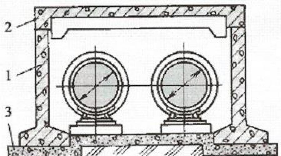
Figure 5.2.2. No-pass channel: 1 - wall block, 2 - floor block, 3 - concrete preparation
Non-passable channels (Fig. 5.2.2) allow you to place only the supply and return heat pipelines in themselves, for access to which it is necessary to tear off the soil layer and remove the upper part of the channel. Most of the heat pipelines are laid in non-passable channels and channelless.
Semi-bore ducts (Fig. 5.2.3) are constructed in cases where constant, but rare access is required to heat pipelines. Semi-bored channels have a height of at least 1400 mm, which allows a person to move in it in a bent state, performing inspection and minor repairs of thermal insulation.

Figure 5.2.3. Reinforced concrete semi-bore
The greatest danger to heat pipelines is corrosion of the outer surface, which occurs due to the effect of oxygen coming from the soil or atmosphere along with moisture; additional catalysts are carbon dioxide, sulfates and chlorides, which are always present in sufficient quantities in the environment. To reduce corrosion, heat pipes are covered with multilayer insulation, which provides low water absorption, low air permeability and good thermal insulation.
Heat network is a system of pipelines through which the heat carrier (steam or hot water) transfers heat from the source (heat generator - boiler) to consumers and returns back: through the same communication system, heat pipelines, called the centralized heat supply system. Construction in this area is one of the most responsible and technically complex works, since laying the elements of the pipeline system in urban and suburban farms makes their repair and emergency recovery very laborious, which makes it necessary to impose increased requirements on the quality of capital construction. High temperatures and pressures require equally high reliability and safety guarantees of heating networks (heating mains).
According to the basic type of device, the schemes of main heating networks are conventionally divided into ring and radial (dead-end). Jumper connections are usually provided between remote backbone networks: so that in the event of an emergency there are no excessive interruptions in the supply of heat. With a very long length of the main heating network, an additional unit is installed in it - a booster pumping substation. For this purpose, underground (where heating networks usually pass, as well as there are branch points), special chambers are equipped in which stuffing box expansion joints and pipeline fittings (shut-off and adjusting structures) are located.
It is the main heating networks that have the greatest length, since they can be removed from the heat source by several kilometers or even more. During the construction of main heating mains, pipelines made of special steels are used (for high-temperature working environments), the diameter of such pipes can reach 1400 mm. In situations where the coolant is supplied by several generating enterprises, the so-called. loopbacks. In fact, they unite all these enterprises into one heating network. Such a solution allows to significantly increase the level of reliability of supply of heat points and, accordingly, the reliability of heat supply to the end consumer. Heating network - a system of pipelines through which the heat carrier (steam or hot water) transfers heat from the source (heat generator - boiler) to consumers and returns back : on the same system of communications-heat pipelines, called the district heating system. Construction in this area is one of the most responsible and technically complex works, since the laying of thermal systems in urban and suburban farms makes their repair and emergency recovery very labor-intensive, which makes it necessary to place increased demands on the quality of capital construction. High temperatures and pressures require equally high reliability and safety guarantees of heating networks (heating mains).

In case of accidents that occur from time to time on highways and in boiler houses, one of the neighboring boiler houses of this heating network is engaged in heat supply to the emergency section of the heating network. In some cases, a planned redistribution of the load between heat generating enterprises is arranged. Water, prepared in a special way, with the given indicators of carbonate hardness, oxygen and iron content, is used as a heat carrier for main networks. Ordinary tap ("hard") water should not enter the main heating system, since its chemical composition at high temperatures leads to accelerated corrosive wear of the pipeline. In particular, in order to prevent this, such a special design as a heating point is envisaged in the projects of heating networks. Normally, such a heating point should be removed from consumers by no more than a kilometer. And within the city limits, this distance reaches, on average, about two blocks.
Heating network
A heating network is a set of pipelines and devices that provide
which transport heat from a heat supply source to consumers by means of a heat carrier (hot water or steam).
Structurally, the heating network includes pipelines with thermal insulation and expansion joints, devices for laying and securing pipelines, as well as shut-off or control valves.
The choice of the coolant is determined by the analysis of its positive and negative properties. The main advantages of the water heat supply system: high storage capacity of water; the possibility of transportation over long distances; compared to steam, less heat loss during transportation; the ability to regulate the heat load by changing the temperature or hydraulic mode. The main disadvantage of water systems is the high energy consumption for moving the coolant in the system. In addition, the use of water as a heat carrier, there is a need for its special preparation. During preparation, the parameters of carbonate hardness, oxygen content, iron content and pH are normalized in it. Water heating networks are usually used to satisfy heating and ventilation load, hot water supply load and process load of low potential (temperature below 100 0 С).
The advantages of steam as a heat carrier are as follows: low energy losses when moving in channels; intense heat transfer during condensation in heating appliances; in high-potential process loads, steam can be used with high temperatures and pressures. Disadvantage: the operation of steam heating systems requires special safety measures.
The scheme of the heat network is determined by the following factors: the location of the heat supply source in relation to the area of heat consumption, the nature of the heat load of consumers, the type of heat carrier and the principle of its use.
Heating networks are subdivided into:
Trunk lines laid in the main directions of heat consumption objects;
Distribution, which are located between the main heating networks and branch nodes;
Branches of heating networks to individual consumers (buildings).
Heating network diagrams are used, as a rule, beam, fig. 5.1. From the CHPP or boiler house 4, through the beam lines 1, the coolant is supplied to the heat consumer 2.  the beaters, the beam lines are connected by jumpers 3.
The radius of action of water heat supply networks reaches
12 km.  With small lengths of highways, which is typical for rural heating networks, a radial scheme is used with a constant decrease in the diameter of the pipes with distance from the heat supply source.
Laying of heating networks can be aboveground (air) and underground.
 Overhead pipe laying (on
free-standing masts or overpasses, on concrete blocks and is used on the territories of enterprises, during the construction of heating networks outside the city limits when crossing ravines, etc.
 In rural settlements, ground laying can be on low supports and supports of medium height. This method is applicable at a temperature of warm
carrier no more than 115 0 C.  Underground laying is the most common. Distinguish between channel and channelless laying. In fig. 5.2 shows the duct laying. In duct laying, the insulating structure of pipelines is relieved from external backfill loads. With channelless laying (see Fig.5.3), pipelines 2 are laid on supports 3 (gravel
or sand cushions, wooden blocks, etc.).
Backfill 1, which is used as: gravel, coarse sand, milled peat, expanded clay, etc., serves as protection against external damage and at the same time reduces heat loss. With duct laying, the coolant temperature can reach 180 ° C. For heating networks, steel pipes with a diameter of 25 to 400 mm are most often used. In order to prevent the destruction of metal pipes due to thermal deformation along the length of the entire pipeline, compressors are installed at certain distances.

Various designs of expansion joints are shown in Fig. 5.4.


Rice. 5.4. Compensators:
a - U-shaped; b- lyre-like; v- stuffing box; G- lens
Type compensators a (U-shaped) and b (lyre) are called radial. In them, the change in the length of the pipe is compensated by the deformation of the material in the bends. In stuffing box expansion joints v sliding of the pipe in the pipe is possible. In these expansion joints, there is a need for a reliable seal design. Compensator G - the lens type selects the change in length due to the spring action of the lens. Great prospects for us with l'fonny expansion joints. The bellows is a thin-walled corrugated casing that allows to perceive various movements in the axial, transverse and angular directions, to reduce the level of vibrations and to compensate for misalignment.
The pipes are laid on special supports of two types: free and fixed. Free supports ensure the movement of pipes during thermal deformations. Fixed supports fix the position of the pipes in certain areas. The distance between the fixed supports depends on the pipe diameter, for example, with D = 100 mm L = 65 m; at D = 200 mm L = 95 m. Between the fixed supports for pipes with compensators install 2 ... 3 movable supports.
Nowadays, instead of metal pipes, which require serious protection against corrosion, plastic pipes have begun to be widely introduced. Industry in many countries produces a wide range of pipes made of polymeric materials (polypropylene, polyolefene); metal-plastic pipes; pipes made by winding a thread of graphite, basalt, glass.
Pipes with industrial insulation are laid on the main and distribution heating networks. For thermal insulation of plastic pipes, it is preferable to use polymerizing materials: polyurethane foam, expanded polystyrene, etc. For metal pipes, bitumen-perlite or phenol-poroplastic insulation is used.
5.2. Heat points
A heat point is a complex of devices located in a separate room, consisting of heat exchangers and elements of heating equipment.
Heat points provide connection of heat-consuming objects to the heat network. The main task of the TP is:
- transformation of thermal energy;
- distribution of the heat carrier among heat consumption systems;
- control and regulation of coolant parameters;
- accounting for the consumption of heat carriers and heat;
- shutdown of heat consumption systems;
- protection of heat consumption systems from an emergency increase in the parameters of the coolant.
Thermal points are subdivided according to the presence of heating networks after them into: central heating points (CHP) and individual heating points (ITP). Two or more heat consumption objects are connected to the central heating station. ITP connects the heating network to one object or part of it. By location, heat points can be detached, attached to buildings and structures and built into buildings and structures.
In fig. 5.5 shows a typical diagram of ITP systems that provide heating and hot water supply for a separate facility.
Two pipes are connected from the heating network to the shut-off valves of the heat point: supply (high-temperature coolant is supplied) and
turnover (cooled heat carrier is removed). Parameters of the coolant in the supply pipeline: for water (pressure up to 2.5 MPa, temperature - not higher than 200 0 С), for steam (p ![]() t 0 C). At least two heat exchangers of the recuperative type (shell-and-tube or plate) are installed inside the substation. One ensures the transformation of heat into the heating system of the facility, the other into the hot water supply system. In both systems, in front of the heat exchangers, devices for monitoring and regulating the parameters and supply of the coolant are installed, which makes it possible to automatically record the consumed heat. For the heating system, the water in the heat exchanger is heated to a maximum of 95 0 C and is pumped through the heating devices by a circulation pump. Circulation pumps (one working, the other standby) are installed on the return pipeline. For hot water supply
t 0 C). At least two heat exchangers of the recuperative type (shell-and-tube or plate) are installed inside the substation. One ensures the transformation of heat into the heating system of the facility, the other into the hot water supply system. In both systems, in front of the heat exchangers, devices for monitoring and regulating the parameters and supply of the coolant are installed, which makes it possible to automatically record the consumed heat. For the heating system, the water in the heat exchanger is heated to a maximum of 95 0 C and is pumped through the heating devices by a circulation pump. Circulation pumps (one working, the other standby) are installed on the return pipeline. For hot water supply

The water pumped through the heat exchanger by the circulation pump is heated to 60 0 С and supplied to the consumer. The water consumption is compensated to the heat exchanger from the cold water supply system. To account for the heat spent on heating water and its consumption, appropriate sensors and recording devices are installed.
A.A. Yakovlev, director,
ON. Orlov, chief metrologist,
I.A. Ionova, head of section number 3,
LLC "Heating networks of Zheleznodorozhny", Zheleznodorozhny
About the Enterprise
The city of Zheleznodorozhny is located 15 km from Moscow; its population is about 120 thousand people.
In 1969, an Enterprise of United Boiler Houses and Heat Networks of the City was created in the city, which initially included only two boiler houses, with a total installed capacity of 34 Gcal / h. These boiler houses supplied the residential buildings of two micro-districts with heat energy and hot water.
Further growth of the installed heat capacity of the enterprise was associated with the adoption of a number of departmental boiler houses on its balance sheet.
In 2007, the enterprise was transformed into LLC "Heating networks of the city of Zheleznodorozhny", after which a lease agreement was concluded with the city administration for a period of 49 years for the entire heating system, which is on the balance sheet of "Heating network".
Today, LLC "Heating networks of the city of Zheleznodorozhny" is leased and serviced by 18 boiler houses, which include 69 boilers with an installed capacity of 379.8 Gcal / h. The company employs about 500 people who are engaged in the maintenance and operation of not only boiler equipment, but also 176.6 km of heating mains in 2-pipe calculation, 36 central heating stations. In accordance with the approved heat supply scheme. The railway company is defined as the Unified Heat Supply Organization in its area of operation.
Heat sources
Most of the boiler houses operated by Zheleznodorozhny Heating Networks LLC were obtained from various departments. This process took place quite actively in the 1990s, after the status of an independent enterprise was obtained. In addition to boiler houses, heat networks were also transferred to the balance of the enterprise. Unfortunately, in most cases, the condition of the transferred heat sources and heating networks left much to be desired. For example, at one of these boiler houses, out of 5 steam boilers, only one could operate, and moreover, only on one burner.
Basically, the enterprise operates hot-water boilers, two of which were at one time transferred from a steam operation to a hot-water one. Due to the lack of sufficient spare funds, the transfer of the remaining seven steam boiler houses has not yet been carried out. It should be noted that when organizing the technological process of transferring from steam to hot water mode, it was necessary to conduct additional training of personnel to work with vacuum deaeration. All boiler houses operate on natural gas according to a temperature schedule of 115/70 or 130/70 O C.
Currently, construction, installation and commissioning works are underway, as a result of which it is planned to commission 5 new boiler houses in the city (Fig. 1).
Rice. 1. Modernized boiler rooms.
The modernization of heating equipment in all boiler houses is ongoing. We have been working with some of our main contractors in this direction for several years. In particular, work was carried out to replace heating surfaces of boilers PTVM, DKVR, TVG, to install modern plate heat exchangers; for the repair and replacement of shell-and-tube heaters, HVO filters. In addition, after the completion of the repair work, the specialists of the company carry out the adjustment of the repaired equipment.
After a long analysis of the automation tools presented on the Russian market, it was decided to use the developments of the domestic production of the software and hardware complex. The deployment of the automation and dispatching system was implemented systematically.
Both small and large boiler houses are automated to one degree or another, first of all, automatic ignition of boilers and further monitoring of their operation parameters are organized. In this regard, the reliability of the equipment, the efficiency and effectiveness of the work of the personnel have significantly increased. Data on the operating modes of the facilities were brought to the operator's workplaces and to the control room. Fast notification of abnormal situations made it possible to timely, remotely eliminate many emerging malfunctions and reduce the number of visits by repair teams (Fig. 2).

Rice. 2. "Battle post" of the boiler operator.
Today, almost the entire range of Russian boilers, both hot water and steam boilers, is in operation. Among them are both classic series, such as PTVM, TVG and KVGM, DKVR and DE, Ziosab, etc., as well as quite exotic ones. For example, at one of the boiler houses, boilers produced at the end of the 19th century are still in working order.
Historical monument
The Lancashire boiler was built in 1896 in England at the Daniel Adamson Du Kinfild plant. Boiler units in the amount of three units were installed in 1896 in the village of Savvino, Bogorodsky district, Moscow province, at the dyeing and spinning factories of the Savvinsky manufactory of Vakula Morozov, the sons of Ivan Molyakov and Co.
In those days, the purpose of these boilers was to generate the steam needed for the dyeing process and to set the steam engine in motion. The first boiler mechanic was Andrei Fomich Oldred.
The Lancashire boiler is a cylindrical steam boiler with two steam pipes and a firebox located at the beginning of these pipes. Combustion products at the outlet of the flame tubes are directed through two side chimneys and exit into a common flue. An improvement in Lancashire boilers was the installation of Galloway boiling pipes in the flame tubes in order to increase the circulation of water from the lower part of the boiler to the upper and to increase the heating surface of the boiler. The Lancashire boiler operates on natural draft (without a smoke exhauster and fan). The cylinder of the boiler consists of sections that are connected to each other with a riveting system, only a small number of rivets and boiling pipes have been replaced during operation.
These boilers operated on fuel oil, the factory had its own fuel oil economy, and they also had the ability to work on coal.
"Lancashire" boilers produced steam for a cotton spinning mill until 1967, after which 2 units were removed from the register in the administration of the central district of Gostekhnadzor of the USSR in connection with the transfer to a hot-water regime with a water temperature of up to 115 ° C.
In 1969, the boilers were converted to gas fuel, and Kazantsev's injection burners were installed instead of the oil injectors. Boiler units, transferred to hot water mode, began to work to provide heat energy to houses where factory workers lived, while one boiler worked for the needs of hot water supply, the other for heating.
In 1985, the boiler house of the Savvinskaya cotton-spinning mill was reconstructed with the installation of a water-heating boiler TVG-4R, and the third remaining steam boiler "Lancashire" was dismantled. Two Lancashire boilers were still in operation at that time (Fig. 3).

Rice. 3. Boilers "Lancashire", general view.
Until now, the passports of two Lancashire boilers have been preserved (Fig. 4), where you can read all the records on their repair. So, when working on fuel oil, there was a large accumulation of soot, scale and rust. Preventive work was carried out for the repair and examination of the examination of the metal of the boilers. When converting boilers to chemically purified water, the amount of scale, rust, the appearance of ulcers in the metal was significantly reduced and thereby increased their service life.

In recent years, before leaving for a well-deserved rest, the Lancashire boilers worked only in the summer season to supply the coolant to the central heating station, ITP of residential buildings, to prepare hot water for the entire microdistrict. Savvino g. About. Railway. Out of respect for the patriarchs, these boiler plants are still in reserve, they can always be put into operation in emergency situations. And the current work of the boilers is still being carried out: inspection, cleaning of internal surfaces, hydraulic tests - as they say: "our armored train ...".
The Lancashire boilers were produced 120 years ago, and, as they say, “for centuries”: their performance has practically not changed over many years of operation, and the main job of the driver consisted only in monitoring the pressure and temperature of the water leaving the boiler during the time of its work.
Heating network
The company's policy in recent years has been mainly aimed at replacing worn-out heating networks in order to increase the reliability of heat supply to the city. Today, the diameters of the operated pipelines of heating networks are in the range from 50 to 500 mm.
Most of the heating networks in mineral wool insulation were laid in the channel. But the operating conditions for canal pipelines in the city are not satisfactory, especially in its central part. This is due to several main reasons: groundwater is located very close, and they are quite corrosive; there are many low-lying and boggy areas in the city; an electrified railway runs through the city. Unfortunately, in the town of Zheleznodorozhny there are places where there is practically no storm sewage and, in fact, the channels of our heating networks often act as elements of this sewage system. In one of the parts of the city - on the high bank of the river. Pekhorka - the soils are sandy and the conditions for canal laying are good - the channels of heating networks are dry. But, unfortunately, this is a very small part of the city and, accordingly, the share of "normal" heating networks for duct laying is also small.
In order to improve the reliability of heat supply to the city, first of all, in its central part, the enterprise practically abandoned the use of duct laying of pipelines of heating networks and switched to channelless laying of pre-insulated pipes, to pipes made of cross-linked polyethylene and flexible pipelines.
To date, more than 35 km of pipes have been laid in polyurethane foam insulation in two-pipe calculation. The technology of channelless pipe laying in polyurethane foam insulation began to be used more than 20 years ago. Pre-insulated pipes and elements for them in polyurethane foam insulation are purchased from different manufacturers by OOO "Zheleznodorozhny Heating Networks", including from the "Vadis-Center" LLC plant located in Zheleznodorozhny, which makes it possible to carry out re-laying in a very short time. heating networks due to the rapid execution of orders by the manufacturer. Sometimes, when replacing sections of pipelines inherited from various departments, our enterprise does not even have technical documentation for them. Therefore, the real picture is often obtained immediately after the opening of the section of the heating networks laid in the channel. And again, the presence of a local supplier of pipes in PU foam insulation helps us to quickly carry out this replacement (for example, when insulating geometrically complex structures), because delivery of pre-insulated pipes and their elements in polyurethane foam insulation takes a minimum of time.
During the operation of pipes in polyurethane foam insulation, no emergencies arose on them. There was some mechanical damage to the PU foam insulation caused by fires at the entrance to the houses, damage during excavations, but naturally the pipelines in the PU foam insulation never failed. This is due not only to the quality of the pipes themselves, but also to the culture of their laying. To achieve the required quality of pipe laying in polyurethane foam insulation, the employees of the enterprise had to work for a very long time and painstakingly with contractor construction organizations, because The requirements for the laying of these pipes are much more stringent than for duct laying of pipes in mineral wool insulation. Only if all the requirements set forth in the relevant regulatory and technical documentation for the high-quality laying of pre-insulated pipes in polyurethane foam insulation are met, their long service life can be guaranteed.
For about 10 years, the company has been using flexible corrugated pre-insulated pipes. Since the inner pipe is made of stainless steel, and a polyethylene waterproofing shell is used as thermal insulation, these pipes operate at temperatures of 115/70 and 130/70 o C. The only problem is their high cost; other issues related to the installation and operation of pipes of this type never arose. Their use is especially important in areas of heating networks with complex gasket geometry.
The presence of the UEC system on pre-insulated pipelines is an integral part of this technology. For the last 7 years, the enterprise has been actively working on the mixing of readings from all local sections of pipelines of heating networks in insulation foam, equipped with an UEC system, to the control room.
The problem of the low "lifetime" of hot water supply pipelines, as in many heat supply organizations, is one of the main problems at the enterprise. In this regard, flexible reinforced heat-insulated pipes made of cross-linked polyethylene, which have been used at the enterprise instead of steel pipes for more than 10 years, have proven themselves very well. In operation, there were no problems with them either, however, there was one curious case - at the entrance to the house in the basement, the "homeless" set fire to a pipe, as a result of which the input burned out. Now, to prevent possible repetitions of such situations, the inputs are “closed”. The only drawback, in the opinion of our specialists, is the limitation of the range of the maximum diameter of these pipes due to the complexity of transportation and installation.
Hydraulic and temperature tests have been carried out on all heating networks for many years. Installations for electrochemical protection of pipelines from stray currents are actively used, due to the presence of a large number of railways within the city. Acoustic leak detectors and thermal imagers are used to detect leaks.
In recent years, the volume of replacement of heating networks in Zheleznodorozhny is significant. This is happening, among other things, due to the implementation of the municipal program for the development of housing and communal services in the city of Zheleznodorozhny, carried out by the city administration in recent years. The administration made the absolutely correct decision: before improving the territory, it is necessary to replace all the communications that are underground.
Heat points
All these years, as it was mentioned above, the main goal of the enterprise is to put in order the heat sources and heating networks, which were inherited from the departmental organizations. Unfortunately, little attention was paid to the reconstruction of the central heating station. The situation has now changed. Since 2010, the enterprise has been implementing the Investment Program "Development of the heat supply system of the Zheleznodorozhny urban district for 2010-2018". The main goal of the program is the reconstruction and modernization of 10 central heating stations located in the area of operation of boiler house No. 7. Within the framework of the program, the following activities are carried out:
■ repair of building structures of heating points with additional insulation;
■ replacement of shell-and-tube heat exchangers installed in the central heating station with modern plate heat exchangers;
■ replacement of pumps with energy efficient ones with a variable frequency drive (VFD).
The enterprise has not yet experienced the transition from the central heating station to the ITP. In our opinion, subject to the normal operation of the existing central heating stations, one should not abandon them in favor of the ITP, due to the high financial costs and a long payback period. Due to the introduction of mixing pumps and the simplest automation for regulating the themes
The temperature of the heat carrier at the central heating station can be used to organize a normal mode of heat supply to buildings, excluding possible "overheating" and "underflooding" in them, which we are implementing. Although the future is undoubtedly for ITP, therefore the issue of using ITP in new construction is not discussed - here its effectiveness is justified.
Metrological group
Currently, the measurement accuracy is in one of the first places in terms of its importance. Accuracy is also required in monitoring the parameters of pressure, temperature, flow rate of water, steam, gas at heat supply facilities and heating networks, and in setting the parameters of automatic safety of boilers and a system for monitoring the content of carbon monoxide CO and CH 4 methane in boiler rooms. Therefore, the need for metrological support is beyond doubt.
The metrology group is part of the instrumentation and control and metrology service of the enterprise. The metrological group employs 6 employees: a chief metrologist, a metrological engineer, a foreman and three adjusters. The existing staff has been formed and strengthened over the years, and now the employees have 18 boiler houses and most of the central heating stations in service. The range of used measuring instruments is very wide and varied. So every year through the hands of employees of the metrological group passes: 2,000 units. pressure gauges for technical, boiler, electrical contact, 300 units. draft gauges and pressure gauges, differential pressure gauges, gas detectors, as well as hundreds of thermometers and pressure transducers of various types. All boiler houses of Heating Networks are equipped with gas metering units, consisting of gas meters and gas parameters correctors, as well as metering units for heat energy, cold and hot water, which need periodic verification at intervals established by the verification procedure.
These measuring instruments must undergo a thorough check, and, if necessary, repair, before being submitted for verification. So in preparation for the heating season 2014-2015. about 500 technical, boiler and electrical contact pressure gauges were repaired, and 105 new pressure gauges were introduced.
Due to the huge number of measuring instruments and the high costs of carrying out their verification, it became necessary to accredit our own metrological service for the right to verify the measuring instruments. For this, two laboratories have been created and equipped. In one of them there is an installation for checking gas meters with a maximum gas flow rate of 6500 m 3 / h and a diameter of up to 400 mm, as well as thermostats, temperature and pressure calibrators for checking various thermometers, heat meters, heat meters and gas correctors. The second laboratory contains deadweight pressure gauges, hydraulic presses, pressure calibrators for checking manometers, pressure sensors, differential pressure gauges, draft gauges, as well as calibration gas mixtures of CGM for checking gas alarms used at heating network facilities. Accreditation was obtained for the right to verify measuring instruments. The total volume of financial investments amounted to more than 500 thousand rubles (Fig. 5).

Carrying out high-quality repairs and verification of measuring instruments for their own needs, and planning their work in a timely manner, the number of visits to facilities to eliminate malfunctions during the heating season has decreased, thereby making it possible to repair and calibrate measuring instruments for third-party organizations.
All repaired and verified measuring instruments are recorded in the database, their calibration schedules are drawn up, coordinated with the boiler house shutdown schedule, thereby there is a constant control over the observance of the measurement accuracy. The company constantly undergoes a process of modernization and updating of the used measuring instruments, forcing employees to constantly improve, studying and mastering modern devices.
The creation of our own metrological service allows us to reduce the cost of checking equipment by 15-20%, and also contributes to the process of modernization and renovation of the enterprise, and the improvement of personnel.
Conclusion
The enterprise plans to work on further replacement of heating networks with pre-insulated pipes, modernization of central heating points and boiler houses, increasing the level of automation of heat and power facilities, commissioning newly built boiler houses with modern equipment and high efficiency. At the same time, despite serious capital investments, tariffs for the population will remain within the approved ceiling level, the work is planned to be carried out at the expense of their own funds obtained as a result of energy efficiency improvements and extra-budgetary sources.
An important direction in the development of the enterprise is the work to improve the payment discipline of residents, the introduction of energy conservation among consumers. The administration of the enterprise devotes a lot of time and attention to improving the social and living conditions of employees, as well as attracting young personnel to the industry. In this regard, the Public Chamber of the city of Zheleznodorozhny, together with the employees of the enterprise, organized "Lessons in housing and communal literacy" for students of city educational institutions. The program provides 36 academic hours, the course will consist of 17 lessons, while the plan includes a visit to the facilities of LLC "Heating Networks in Zheleznodorozhny". In addition to obtaining basic knowledge in the field of housing and communal services, these classes will help schoolchildren to professionally orient themselves and, possibly, choose our company for further professional development.