Regenerative steam selections as a hidden rotating power system reserve. For nominal parameters of steam, adjustable selections and power
Page 1.
Adjustable selection of steam is made from below from the exhaust pipe of the high pressure cylinder at a pressure of 6 - 8 at. In addition, there are two unregulated selection in a low-pressure cylinder after the 10th and 13th steps, of which the pairs enters the heaters of the feed water. A steam heater is heater comes from an adjustable selection over the amount coming to production.
Adjustable selection of steam in Tourbin type AP has a production assignment; Turbine AT has adjustable selection is designed for heat purposes.
The adjustable selection mode of the steam should be so that the turbine always worked with the sampling value close to the nominal one. With a small selection, it is necessary to check the economic reasonableness of saving the turbine installation in operation.
The pressure of the adjustable selection of the steam is the pressure of steam in the selected turbine nozzle before the shut-off valve.
The pressure of the adjustable selection of the pair is called its pressure in the turbine housing pipe through which the selection is made. The nominal value of the selection is called the largest number of steam turbines, which must be provided at its rated power.
The turbine had adjustable selection of steam (having a value for the heated) from 1 to 2 Ata.
Turbines without adjustable pair selection are marked by a seating.
The nominal value of the adjustable selection of steam from a turbine with one adjustable selection is the highest selection value in which the turbine develops the rated power; The turbine with two adjustable steam selection should develop rated power at the nominal values \u200b\u200bof both adjustable selections.
Rotary diaphragms of adjustable steam selections are checked before installation in the turbine cylinder. For this, the assembled diaphragm is placed on the lining so that the side of the input of steam into the nozzle is located on top. Then the rotary ring is collected on the diaphragm and the density of sealing belts is checked through its windows. Plate of probe thick 0 05 mm should not pass into their joint. The required joint density is achieved by rolling belt first by paint, and then in shine.
Turbines without adjustable selection steam marked with an asterisk.
Rotary diaphragms of adjustable selections of steam are checked until they are installed in the turbine cylinder. For this, the assembled diaphragm is laid on the lining so that the side of the input of the steam into the nozzle of the diaphragm was located on top. Then the rotary ring is collected on the diaphragm and the density of sealing belts is checked through its windows. Plate of probe thick 0 05 mm should not pass into their joint. The necessary junction density is achieved by rig tape: first by paint, and then in shine.
When reserving adjustable selections of steam or backpressure of thermal turbines, automatic inclusion is especially necessary in cases where the requirements of the production technology are not allowed in steam supply.
Turbines without adjustable selection steam marked with an asterisk. The values \u200b\u200bof the parameters enclosed in brackets are not recommended for newly designed turbines.
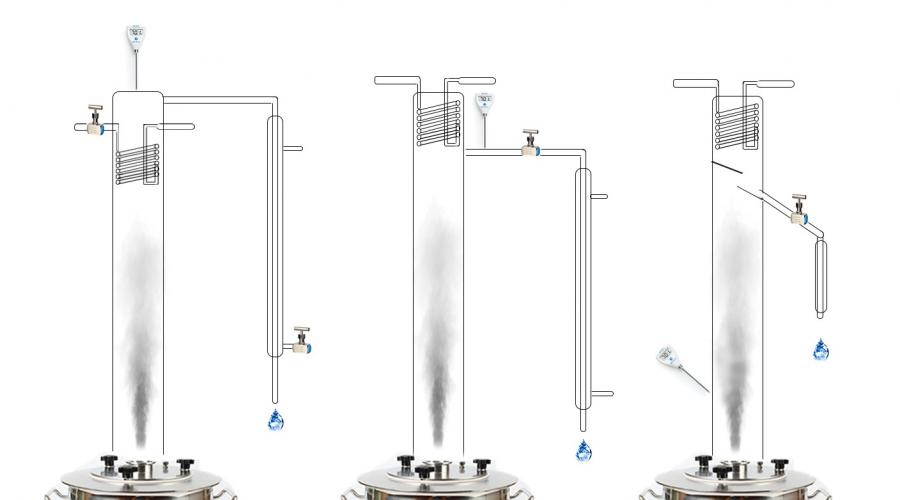
A comparative analysis of three selection schemes that are used in homemade and distillation collens. The characteristics, advantages and disadvantages, as well as applicability in various distillation options are considered. Each method corresponds to its type of equipment.
To work successfully with a column, you need to adjust the phlegm number. For this there are three methods:
- CM (Cool Managment) - water flow control supplied to the cooling of the reflux;
- Lm (Liquid Managment) - control of the number of phlegm selected (fluid selection);
- VM (VAPOR Managment) - control of the number of pair of selected (pair selection).
 Methods for managing a distillation column
 Before starting a conversation about the types of selection, we will define the terms.
Distillation - The process of evaporation of fluid with subsequent condensation.
If initially the raw materials were evaporated from a distillation cube, then condensed it in the refrigerator (condensor), so that neither the insertion of this process (the passage of steam through the height, the bubbler or reflux), ultimately it will still be distillate.
Rectification - This is one of the distillation methods, which distinguishes two technological receptions:
Forced, strictly adjustable refund refund with special devices - deflements or condenses.
It is organized a heat and mass bond between phlegm and a ferry rising towards. To increase the efficiency of thermal basisman, use the nozzle or plate columns, where the reflux of phlegm occurs. In the first case, the process is filmted, in the second - bubble.
The purpose of rectification is to obtain alcohol of a given fortress and its purification from impurities. For this, the phlegm number should always be higher than the minimum (details on the chart).

The quality of the product depends on the magnitude of the phlegm number, but the higher the performance of the column.
Rectification does not allow to allocate any mixture from the group, but only more or less completely removes the impurities grouped over close volatility. Therefore, if you use distillation equipment for obtaining, for example, fruit distillates, there is a risk to group a head fraction in difficult-shared azeotrops - remove with unnecessary impurities the useful esters responsible for the fragrance.
If trying to drive out the noble distillate on distillation equipment, it is necessary that during the entire selection the phlegm number did not exceed 1.5-2. Otherwise, the balance of impurities will be broken.
Types of selection nodes in the column
Liquid selection (Liquid Managment)
LM - adjustment of the amount of fluid selection. The most convenient and easy-to-use diagram at which all pairs are condensed, then one part of the condensate returns to the column, the other is in selection.
Characteristics. The adjustment of the phlegm number is carried out by one needle crane of the selection of alcohol. If the valve is fully open, the phlegm number is zero, and the output is the usual distillate. With the closed crane, the phlegm number is infinitely large - the column works on itself. Adjusting the faucet of the liquid selection allows you to change the phlegm number at any time from 0 to 100%. The heating and cooling capacity is set at an optimal level, providing the maximum separation ability of the column and the minimum cooling of phlegm.
Liquid selection columnAs a rule, the phlegm number is set slightly higher than the minimum that when selecting the "body" allows for a relatively long time without adjustments, but closer to the end of the selection still have to actively adjust the process. At the same time, the less alcohol remains in Cuba, the more often the phlegm number has to increase.
Benefits:
- suitable for obtaining both fragrant and clean alcohols;
- easily and relatively cheaply automated up to the ACS (automated control system) process of production with safety blocks;
Disadvantages:
- if you fix the selection speed at the same level, then as a rectification, a phlegm will fall. This contradicts the technological need to gradually raise the speed by the end of the selection, which is the main disadvantage;
- we are required to break the jet (connection with the atmosphere) after adjusting the crane or valve, otherwise failures in adjusting the selection rate due to the discharge in the selection line, which creates flowing alcohol flows.
VAPOR MANAGMENT
VM - adjustment by the separation of steam streams to a reflux. The column control is carried out by changing the number of selected steam using a wishing or conventional ball valve.
Characteristics. The ratio of the cross-sectional area of \u200b\u200bthe column and the steaming pipe defines the minimum phlegm number, which can be increased by adjusting the position of the crane.
 Steam column
 When distillation, the amount of reflued phlegm is adjusted from 80 to 100%. The minimum possible phlegm number is 4.
Benefits:
- the sensitivity to the position of the crane is quite small, which allows you to make accurate adjustments;
- the phlegm number does not depend on changes in temperature or cooling water consumption in a reflux;
- there is no increased sensitivity to the stability of the cooling water pressure.
Disadvantages:
- the inertial control system, from changing the position of the crane before changing the selection speed, can pass to 10-15 seconds;
- not suitable for obtaining fragrant alcohols from natural raw materials. Constructive changes are required to adjust the amount of reflued phlegm from 50 to 100%;
- the column with steam selection is sensitive to traffic jams on the product selection line. If a product column is formed in the silicone hose, it will create a discharge, and as a pump will pull steam on itself, disturbing the installed phlegm number. As a result, the selection rate will increase sharply and uncontrollable, the system will not return to the previous level without interfering. Stop uncontrollable selection can be installed with the atmosphere (create a jet break). For example, stick the needle from the syringe to the top of the selection tube;
- automation is complex and road. It is often performed in the form of an alarm device for achieving certain temperatures, but without actuating mechanisms. Safety automation is also desirable.
Cooling Management (Cool Managment)
Cm - adjustment of the amount of water supplied to the reflux. Allows you to control the amount of steam passing through the reflux of the product selection refrigerator.
Characteristics. The phlegm number is adjusted from 0 to 100%, but the system is very sensitive to the amount of water supplied and requires a precision needle crane. To regulate the selection speed, it is necessary to rotate the faucet literally on the lobe of the millimeter. Heating power during the entire process should be constant and ensure the maximum separation ability of the column. With an increase in the amount of water supplied, the amount of reflapable phlegm increases, respectively, the phlegm number increases.
 Column with water supply adjustment to a reflux
 During the rectification on a constant power of cooling and heating, a gradual decrease in the selection occurs, but the phlegm number remains unchanged.
Advantage:
- it can be successfully used to obtain fragrant alcohols from natural raw materials.
Disadvantages:
- the slightest pressure fluctuations lead to a change in the speed of the selection and a phlegm number. If you do not take measures to stabilize the pressure of cooling water in the apartment, the selection process will be influenced even closer to the neighbors of the toilet;
- increasing the temperature of the water in a deflegmator with its unchanged amount reduces the phlegm number, so it is necessary to control the flow and temperature of the water supplied to the deflegemaker to maintain a stable phlegm number;
- communication with the atmosphere in the product selection line is required, otherwise, in case of accidental disconnection of heating and tube, immersed in the selection, the whole product will be in Cuba again;
- system road and complex in automation. Usually, such distillation columns put the simplest thermosalizers and security automation.
Practice installation of different selection nodes for columns
Columns with liquid selection (LM)
In the domestic columns, the selection on the liquid was widespread. The reason is simple - the process of distillation of 40 liters of the mogon is delayed by 18-20 hours. You can reduce the dump by half, but then the proportion of a revolving (technical) alcohol increases sharply, which will have to be processed with each rectification.
If we talk about the performance of the system as the number of commodity alcohol obtained for the total rectification time (including heating), then with a decrease in the volume of the nut 2 times, the efficiency decreases by about 1.5 times.
Another way to minimize the volume of the resulting technical alcohol at maximum performance is the automation of the process to make distillation according to a predetermined algorithm without the participation of the operator. The automation system must have not only an executive circuit, but also a security unit that instantly turns off the equipment in the threat of an accident.
The distillation column with liquid selection is easier and cheaper than other systems, and according to the quality of the resulting alcohol, it is not inferior to other types of equipment.
Columns with steam selection
Selection systems for a couple are common abroad, where the alcohol and its derivatives are inferior in popularity of distillates (brandy, whiskey, etc.), but the high fortress of the drink is valued. Foreign craftsmen design distillation columns with steam selection having a minimum phlegm number - only 1, and not 4 as in Russia. With such a scheme, at least 50% of phlegm takes place back into the column.
In distillation mode, steam selection practically does not need automation. The phlegm number specified at the start of the selection of the "body" is stored unchanged to the end, only the operator can change it, but even upon receipt of alcohol, the adjustment is just a couple of times.
The speed of selection by the end of the distillation sharply decreases until the stop. If there is a desire to enhance the enantive ether (largely create organoleptic properties of fruit distillates) - change banks and increase the heating power, follows the fractional selection and sorting.
If the enantive ethers are not required, do the same, but additionally use pauses to work the column for themselves, so that the remnants of alcohol are more concentrated and with fewer impurities.
Automation in steam selection columns is needed only at the security block level. In addition, the production of distillate provides non-grouping of impurities in fractions and their complete removal, and a balanced decrease in the concentrations of substances to an acceptable level with the mandatory preservation of flavor-aromatic components. This is the case for the Master-Vinurg, which controls the process, adjusting the instruments here is inappropriate. The navalka is limited by the volume that can be overtaken under the leadership of a person for the existing time.
Columns with water supply adjustment to a reflux
Despite all the flaws, this type of equipment is often used in Russia during the construction of the brighted columns. The reason is the possibility of obtaining distillates from any raw material, and if necessary, without changing the design (an additional kard does not count), you can collect a high degree of cleaning distillate - almost like alcohol.
Columns with adjustment of water supply to the reflux of the road in automation, sensitive to the pressure and temperature of cooling water, which makes them weakly suitable for obtaining pure-spectrum alcohol, but at low dumps up to 20 liters and the emergency attention of the operator, such columns are capable of much.
In addition, the COOL Managment scheme is the best for the selection of "heads." Upcable conditions, it is impossible to obtain more concentrated "heads" on the selection systems on the pair and fluid. True, it is only if you cope with the stabilization of temperature and pressure of water in a reflux.
In recent years, attempts have been made to create hybrid distillation columns, in which the "heads" are selected by a pair of CM method, and the "body" on the liquid (LM). This increases the already high quality indicators of alcohol on LM columns. There are no boundaries for perfection.
When building brighted columns oriented on fragrant distillates, VM equipment has an advantage over the SM due to ease of control, as well as insensitivity to the temperature and flow of water in a reflux - more predictability in "combing" impurities. For sugar raw materials, the removal columns according to the scheme for see more than better removal of the head fraction. But the management of them creates a lot of problems.
From (16.1), an expression should be impressed to determine the consumption of fresh steam into a turbine at the well-known values \u200b\u200bof the power of the turbine and the consumption of steam on thermal consumption:
Turbines with adjustable selection of steam have the following features:
1. Depending on the thermal load possible condensation and heatmodes. For the heat mode, depending on the heat load, the turbine can work on thermal or electrical graphics. In the first case, the regulatory bodies are in a fixed state, and the change in the load of the thermal consumer and the power of the turbine is provided by the ChVD steam distribution authorities. At the same time, it is possible when the regulatory bodies are closed and all pairs are sent to the thermal consumer. In Cund, only the ventilation consumption of steam is sent to cooling its body and rotor. In the modes of electrical graphics, the regulatory bodies of the Cund may have an arbitrary degree of discovery.
2. To prevent emergency situations on the steam liner associated with the adjustable selection chamber, a safety valve is installed. In addition to it, due to the large volume of steam pipelines, check valves are required to prevent the steam pass into the turbine during its emergency stop.
3. In turbines with adjustable selection of water vapor due to the variety of modes, a nozzle pair distribution is used.
The diagram of the turbine modes with one adjustable pair selection Shown in Fig. 16.6.
The power of the turbine determined by the curve aB, it consists of working with a complete selection of steam to the heat consumer ( G. 2 =G. K \u003d 0). Ventilation passage of steam in Cund (5-10% of the calculated value) is determined by the line a 1 B 1. Mesh dotted lines ( a 1 B 1) Determines the operating modes of the turbine with various selection of steam to the heat consumer (chart area a12BA.). Line a 11 B 11 Represents the change in the power of the turbine at the calculated passage of steam in the Cund (when the regulatory bodies are fully open and pressure p P. (r T) supported constant). Line b2.specifies the mode of operation with the maximum passage of steam through Chvd. Line a 1 2. Corresponds to a purely condensation mode of operation when the consumption of steam into the selection is zero. With the calculated passage of steam through the highest power of the turbine is determined by the point b 11. (here is the consumption of steam through Chvd maximum, and the settlement pass through the Cund is equal G. 20 =0,4G. 10). Point a 11. It corresponds to the calculated passage of the steam in Cund under condensation mode and determines the significantly lower power of the turbine, which it can develop with maximum flow rate through Chvd.

Fig. 16.6. Diagram of turbine modes T with adjustable pair selection
If you allow an increase in the pressure of steam to the Cund (in the adjustable selection), then it can be skipped with a greater steam consumption and even with condensation mode to reach maximum power. N Mak. C, which is calculated by the electric generator. In the mode diagram when pair pass G. 20 =0,4G. 10, which corresponds to the line a 11 B 11The adjusting valves of the Cund (or rotary diaphragms) will open completely and further increase the flow rate across the Cund is achieved due to the growth of steam pressure in the chamber of the adjustable selection.
To determine the flow of the selected steam in random mode (point BUT In fig. 16.6) The following construction is performed. Point BUT The diagram defines the consumption of fresh steam into a turbine for a given mode ( G. 1 =G. o). Holding through the point BUT Line permanent passage of steam in Cund, we will find at the crossing line AU with a condensation mode line INwhich allows you to determine the passage pair G. 2 in Cund. The consumption of the selected steam is like a difference G. n \u003d G. 1 -G. 2. Lines of turbine modes with constant consumption of pair of selected G. P \u003d const The diagram is represented by thin solid lines. Sometimes in diagrams instead G. P ( G. T) constant thermal load lines are built. Q. T \u003d. G. sv ( h pr -h about) defined by the values \u200b\u200bof the enthalpium straight ( h pr.) and reverse ( h Ob.) Network water passing through a network heater.
The represented turbines are performed as an intermediate overheating of steam, and without it. Winning from Primegrezhev here is less than that of condensation turbines, as it is determined in relation to the characteristics of the CND, the average annual steam consumption through which in turbines with adjustable selection is less. For turbines with a production selection of a steam, which changes little throughout the year, it is advisable that the condensing power is equal to the nominal value, and not more of it, which is characteristic of turbines with steam heating selections. The dimensions of the last stage of such turbines, with other things being equal, are less than that of condensing, since turbines with heat turbines, installed usually in the city, have an increased temperature of the cooling water and, accordingly, increased pressure in the capacitor with a revolving water supply of the condenser.
On the last page of this lecture, a simplified diagram of modes, which we will use when solving tasks in practical classes are given. It must be printed and bring to practical classes.
1 Question Explain to which stations (Couple-selection) from the turbine
Adjustable selection of a steam from the turbine used to supply consumers with thermal energy.
CHP Para Selection
Production heat intake steam from a turbine used for production purposes
Condensation turbines.
Probably, this type of turbines is the most common (marking - K). Complete with the most turbine itself, there is still a device for collecting the spent pair - a condenser. All spent steam in such a turbine enters the capacitor.
Condensation steam turbines are designed to generate electricity. Those. Such turbines put the Narraces. The CHP put, mostly another type of turbine. All couples from the boiler entered such a turbine makes work for electricity. Heat energy from such turbines does not receive, with rare exceptions.
Heat-effect turbines.
Type turbines - T. This type of turbine is installed on the CHP, i.e. Where, in addition to the generation of electricity, it is still necessary to obtain heat energy - heating and hot water supply.
Cellular turbines have adjustable heat selections. Adjustment is carried out by a rotary diaphragm. Couples with such a selection enters the network heaters - heat exchangers, where the steam transmits its heat of the network water.
Thermal turbines tend to work in condensation mode, for example, in summer. In this case, steam on network heaters does not come, and the whole is used to generate electricity.
Cellular turbines with industrial selection of steam.
Marking such turbines - PT.
Industrial selection of steam means that part of the couple from such turbines goes on any third-party production (factory, factory, etc.). Couples can return back to the power plant in the form of condensate, and maybe completely lost.
Such turbines are currently practical not set. In Soviet times, they were installed at the CHP near large industrial enterprises - chemicals, woodworking factories, etc.
Tour turbines.
The reproductive turbines have labeling - R. in the composition of such turbines there is no condenser, and all the spent pairs goes with some small pressure to a third-party consumer.
This type of turbines is currently, as well as PT turbines, does not find the use of rare exception. After the collapse of the Soviet Union, many such turbines "dust" without affairs, since there was no external consumer of the spent steam. Without consumer, the couple is impossible and their operation, which means that the production of electricity.
2 question circuit UzO
Each protective-disconnecting device, depending on the parameter to which it reacts, can be assigned to one or another type, including the types of devices that react to the voltage of the housing relative to the Earth, the ground shortening current, the phase voltage relative to the Earth, zero voltage Sequences, zero sequence current, operational current, etc. The following are two types of such devices as an example.
Protect disconnecting devices that respond to the voltage of the case relative to the Earth have an assignment to eliminate the danger of damage to the current when the increased voltage is occurred on a grounded or entangled. These devices are an additional measure of protection against grounding or reducing.
The principle of operation is a quick disconnection from the installation network if the voltage of its body relative to the Earth will be higher than some extremely valid value of the UK. DOP, as a result of which touching the body becomes dangerous.
Schematic diagram of a protective-disconnect device that reacts to the voltage of the case relative to the Earth: 1 - housing; 2 - circuit breaker; But - the coil disabled; H - voltage relay maximum; R3 is the resistance of the protective ground; RB - Auxiliary Ground Resistance
3 Question The permissible modes of operation of transformers under normal conditions and emergency situations in the power system
The normal modes of work are considered to be the transformer and in which it can work for a long time with the devices permissible or technical conditions, the deviations of the main parameters (voltage, current, frequency, temperature of individual elements) and normal conditions (climate, installation height above sea level) . The nominal values \u200b\u200bof the main transformer parameters are indicated on its shield and in the passport
Operation of the transformer is allowed only under the condition of the protection of its windings with valve arresters or overvoltage limiters,
Neutral windings of the highest voltage of transformers with a voltage of 110 kV, with incomplete insulation on the side of neutral, should be grounded tightly, except in cases due to P.7.1.5. Transformers with voltage up to 35 kV can work with an isolated neutral, grounded through an exhausting coil (exhausting reactor). With the total current of the exaggeted coils more than 100 and attach them to one transformer follows the coordination with the manufacturer.
The long-term operation of the transformer is allowed at power no more rated when the voltage is exceeded, summing up to any branch of the winding of the VN, CH and NN, 10% over the nominal voltage of this branch of the winding. At the same time, the voltage on some kind of transformer winding should exceed the largest operating voltage for this voltage class.
Load modes
Depending on the nature of the daily or annual workload chart and the cooling temperature temperature, systematic and emergency transformer overloads are allowed. Permissible systematic overload exceeds the nominal load of the transformer, but they do not cause a reduction in its service life, since the wear of the twist isolation does not exceed normal. The permissible transformer emergency overload causes increased, in comparison with normal, wear of the cooker isolation, which can lead to a reduction in the deadline for the transformer service if the increased wear with time is not compensated by the load with the wear of the cooker isolation below normal.
Such overloads are permissible for all cooling systems, regardless of the preceding mode, the temperature of the cooling air and the installation site of the transformers, provided that the oil temperature in the upper layers is not higher than 115 ° C. In addition, for oil-filled transformers operating with the initial load coefficient K1< 0,93, допускается перегрузка на 40 % сверх номинального тока не более 5 суток на время максимумов нагрузки общей продолжительностью не более 6 ч в сутки при принятии всех мер для усиления охлаждения трансформатора.
With a variable load on a substation with multiple transformers, you must create a chart of inclusions and disconnecting parallel transformers in order to achieve economical modes of their work.
In real conditions, it is necessary to deviate from the settlement regime so that the number of operational switching of each transformer does not exceed ten over the day, i.e. it would not have to turn off the transformers in less than 2-3 hours.
With parallel operation of transformers, the total load on the transformer substation should provide sufficient load to each of them, which is judged by the indications of the corresponding ammeters, the installation of which for transformers with a nominal power of 1000 kVA and above is required.
Modern heat and turbines 50 MW and above have two heating adjustable steam selection for stepped heating of the power water carried out in several sequentially located heaters. The pressure of the selected steam is determined by the water temperature at the outlet of each stage of heating. 70-80% of the consumption of steam per turbine are used to heal the network water, and the heating temperature is 40-50 ° C.
Concept of turbine installation with two heating selections (top 4 and Lower 5) is presented in Fig. 20.2, a. Fresh couples in quantity G. about and with parameters p 0, t 0.sums up to the turbine through locking 8 and regulating 7 valves. In Chvd. 1 Couples expand to pressure in the lower heating selection 5 and then through the regulating body 6 headed in Cund 2. The rest of the equipment of turbines with two heating seats of steam is similar to a turbine with two adjustable steam selection (Fig. 20.1).
Fig. 20.2. Schematic scheme (but) and steam expansion process (b) in h, S. -Diagram turbine stop with a two-stage selection of steam.
To the top selection 4 Couples with flow G. 1 Selected at pressure r 1 and with enthalpy h. 1 (Fig. 20.2, b), and in the lower - pairs with a flow rate G. 2 When parameters r 2 and h. 2 . Since the turbine has only one regulating body of the Cund, the adjustable pressure can only be maintained in one of the two heating selections of steam: in the upper - with both selections included, in the lower - with the downstream.
Installation for heating the network water consists of two heaters (boilers) 9 and 10 Surface type. The required temperature of the network water directed to the thermal consumer is determined by the pressure steam pressure of the upper selection. The distribution of heat load between the upper and lower sections is determined by the temperatures of the mains water before and after the network heaters, the flow rate of the power water and electrical load.
Internal power of turbine N I. , kW, with two heating selections The steam is determined from the expression (excluding regenerative selections)
N I. \u003d N. E. / η M. η EG \u003d N. I. "+ N. I. "" + N I. """ =
\u003d G O. N. 0 "η 0i. "+ (G about – G. 1 ) N. 0 ""η 0i. "" + (G about – G. 1 –G. 2 ) N. 0 """η 0i. """ (20.3)
, kW, isQ T \u003d W C C (T 2C -T 1C) \u003d G 1 (H 1 -H 1 " ) + G 2 (H 2 -H 2 " ), (20.4)
where G. about , G P. ,G T. - steam consumption on the turbine, to the upper and lower heating selections, kg / s; N. 0 " , N. 0 "" , N. 0 """- The disposable steps of the turbine to the top selection, between the selections and the Cund , kj / kg; W S. - power supply consumption, kg / s; c B.\u003d 4.19 kJ / (kg · k) - water heat capacity; t 2C, T 1C - water temperature at the entrance and outlet of the heaters, hail; h 1., h 2. - Enthalpy couple in the upper and lower heating selections, KJ / kg; h 1. " , h 2. " - Enthalpy condensate of heating couple in heaters 9 and 10, KJ / kg.
Turbines with two-stage selection of steam can have a variety of heat modes of operation depending on the ratio of thermal and electrical load. Under the modes of work on thermal graphics with a given thermal load Q T. regulator 6 Before the Cund is closed. The power of the turbine is determined by thermal load, and the steam consumption is limited to the value. G Kmindetermined by the conditions for reliable operation of the turbine. When working a turbine for electrical graphics It is possible an independent change in thermal and electrical load. Regulator 6 open partially or completely, which allows for constant heat load to skip through the turbine an additional consumption of a fresh steam entering through a Condenser 3 (Fig. 20.2). This consumption ensures additional power compared to the mode of operation on thermal graphics with the same heat load. Thus, steam consumption across the pounts depends on the specified electrical load.
20.3. The use of built-in beams in condensers of heat turbines
In turbines with adjustable selection of steam, zero passage of steam into the capacitor is not allowed under modes of operation with heat load. Minimum skipserving for cooling steps Cund, is determined turbine design (sizes of buckling Cund, density of regulatory bodies, etc.) and the mode of its work (Vacuum, pressure in the selection chamber).
The heat of the steam entering the condenser is transmitted to circulation water and is not used in the power station cycle. Circulation water is also transmitted by the heat of the steam entering the heat exchangers located on the recycling lines: the gland heater and ejector refrigerators. To utilize this heat, commensurate with the warmth of the maximum passage of steam into the condenser, part of the condenser surface is highlighted in a special heat bunch. In the beam tubes, a substitution of both circulation water and water networks is provided. The surface of the built-in beam is approximately 15% of the total surface area of \u200b\u200bthe condenser.
The design of the condenser with a built-in bundle having independent water chambers and the large surface of the steam space is a typical solution for thermal turbines with a capacity of 50 MW and higher.
Schematic diagram of turbine installation with built-in heating beam in the condenser Presented in Fig. 20.3, a.To the main beam of the capacitor pipes 8 It is provided for the supply of only circulation water, and to the built-in beam 11 - Circulating water and water heat networks (reverse network or support). The rest of the turbine equipment has the same purpose and an image, as in a turbine unit with a two-stage pair selection (Fig. 20.2).
On mode with condensation power generation In the main and in the built-in bundles only circulation water comes. When working on thermal graphics The supply of circulation water to the main and built-in beam is turned off, and the built-in bundle is cooled with a network or feeding water. In this case, the regulator 6 Cund. 20.3 A) closed, and the turbine operates in mode similar to the process of operation of the turbine with a backpressure.

Fig. 20.3. Schematic diagram (a) and steam expansion process (b) in h, S. -Diagram turbine installation with two-stage pair selection and built-in heat beam.
At the same time, the possibility of an independent task of thermal and electrical loads is eliminated, since the electrical power of the turbine, with this mode of operation, is determined by the value and parameters of the thermal load.
Translation of a turbine to work using a built-in beam causes redistribution of pressures and heatpads along the steps of the turbine. In fig. 20.3, B depicts a thermal process of steam expansion in a turbine in h, S. -Diagram when working on condensation (Stroke lines) and with included insulated beam (solid lines). For Chvd turbines working on the built-in bundle associated with an increase in pressure in adjustable selection ( r 1 >r 1 "; r 2 >r 2 "), What leads to a reduction in the power produced on steam streams in the selection. In the case of the turbine, due to the deterioration of the vacuum in the capacitor, the disposable heat transferpad ( H 02 "\u003e H 02 ), and its steps work with a great speed of speeds and / s f and smaller efficiency. In some cases, energy losses in Cund are higher than its disposable heatpad and a chance of the Cund, work with negative efficiency and consume power (line 1-2 in fig. 20.3, b). With such modes due to an increase in the temperature of the steam passing through the Cund, the temperature regime of the exhaust pipe of the turbine deteriorates.
SRS. Figure diagrams
In general mode diagram expresses in graphical form relationship between the electric power of the turbine N. I., steam consumption G. about, heat load consumer Q P. (Q T.), the pressure of the couple released by the consumer r P (r t), Fresh pair parameters p 0, T 0, cooling water consumption W. from et al., defining the operation of the turbo installation:
F (n e, G. 0 , W. C, Q P, Q T, r p, p t ...) \u003d 0. (1)
Equation (1) is graphically represented on the plane if the number of variables does not exceed three. Otherwise, the image of the mode diagram on the plane can only be obtained when replacing the actual relationship of variables by approximate dependences, which makes the error in the diagram, the greater the longer the number of variables equation (1). Therefore, it is advisable to limit the number of independent parameters involved in the modes diagram. When limiting the number of variables of equation (1), it is taken into account that the influence of individual parameters to the power is not equally. To provide ultimate high accuracy the mode diagram is performed in the form of several independent graphs.. Main graphic, Usually called diagram of modes , expressing dependence between turbine power N E. and steam consumption G. 0 . Additional graphs, referred to correction curves to the modes diagram The effect of the change of each of the remaining parameters of equation (1) to the power of the turbine is determined. IN the composition of the mode diagram includes Also some auxiliary curves: The dependence of the temperature of nutrient water from the consumption of fresh steam, a possible minimum pressure in the adjustable selection of steam and selection costs, etc.
The main diagram can be made with high accuracy, since the number of variables is limited. The correction curves usually perform with some error. However, the accuracy of the correction curve slightly increases the overall error of the regimens diagram, since the absolute value of the amendments themselves is usually a few percent of the total power of the turbine.
The presence of the modes diagram allows you to graphically establish the relationship between the parameters of the equation (1) and select the area of \u200b\u200bpossible operating modes of the turbo system. Visuality of the presentation, convenience of use and sufficient accuracy determined the widespread use of the diagram of modes in the design and operation of thermal power plants.
SRS 19.1. The diagram of the process of turbine with a backpress type R. The mode diagram expresses fresh Couple Dependency G 0 from electrical power N E. and backpressure p P. :
G 0 \u003d F (n e, r n). (2)
which can be represented on the plane in accordance with the existing experimental or calculated data. Of the three parameters of the equation (2), the smallest effect has the final pair pressure p P. and therefore the diagram of the process of turbine with a backpressure is performed (Fig. 19.1 SRS) in the form of mesh curves G 0 \u003d F (n e) , obtained by the intersection of the three-dimensional surface described by equation (2), planes p P. = const..

Fig. 19.1 SRS. The diagram of the process of turbine with a backpressure.
SRS 19.2. The diagram of the turbine modes with one adjustable selection of steam. In the general case, the regimens diagram expresses electric power dependence N E. From the consumption of steam on the turbine G 0,in the selection G P.and pressure steam in selection p P..
G 0 \u003d f (n e, g n, p P.). (3)
From this equation, you can exclude the selection pressure p P. When replacing its influence with correction curves that can be made with a relatively small error. Then the dependence (3) can be built on the plane in the form of a series of curves G 0 \u003d F (n e) for G P. = const..
Consider an example of constructing a circuit diagram of a pair of steam selectionapproximate method based on the use of linearized dependency consumption steam on turbine G 0 From power N E. and consumption steam in selection G P.:
G 0 \u003d G co + y p g p \u003d g kk + r to n e + y p g n \u003d g kk + d n (1- x) N e + y n g (4)
where G Co. = G kk + r to n e - steam consumption on a turbine during condensation mode without selection; G k.kh. - steam consumption at idle course of the turbine without selection; r K. =( G 0 - G k.kh. )/ N E. - a specific increase in steam consumption under condensation mode, kg / (kWh · h); y P. = (H P -H K) / (H 0 -H K) - the ratio of the heatpaders of the TPD and the entire turbine (the coefficient of occurrence of power by ferry of selection); d N. = G. Nom/N. Nom - specific steam consumption at rated load and condensation mode of operation, kg / (kWh); x \u003d G H.H. /G 0 - idling coefficient.
The basis of the modes diagram are boundary lines built for the most characteristic modes of the turbine.
Condensation mode. Mathematically dependence of the consumption of steam from power is determined by the expression (5) G P. =0:
G 0 \u003d G Ko \u003d G K.H + D H (1- x) N e (5)
Graphically (Fig. 19.2 SRS) Building a condensation mode line is made by two points: point TO, The ordinate of which corresponds to the maximum passage of steam into the capacitor at rated electrical power N. Nom, and point O 1. determining the consumption of steam on the turbine G k.kh. at zero power (idling). On the abscissa axis, the condensing mode line passing through points TO and O 1. , Cuts cut O O 2. , conditionally determining the loss of the power of the turbine Δ N H.H. On overcoming idling resistance.
In fact, addiction G 0 \u003d F (n e) with a condensation mode, it differs from straight and has a more complex species, determined by the steam distribution system, the nature of the change in the inner relative efficiency, the temperature of the pair spent in Chvd and so on.
Mode of operation of the turbine with a backpressure. Changing the consumption of steam on the turbine is determined by the expression (5) when G K. =0 and G 0 =G P.:
G 0 \u003d G O.P \u003d G p \u003d g k.h + d n (1- x) n e + y n g 0,
G 0 \u003d G kk/(1- y n) + d n (1- x) n e /(1- y n) \u003d g P.H + R n e (6)
G co + y p g p \u003d g kk + r to n e + y p g n \u003d g kk + d n (1- x) n e + y n g
where G P.Kh. = G k.kh. /(1- y n) - steam consumption for idling with referred control, kg / s; r P. = r to (1- y n) - The specific increase in the consumption of steam during the operation of the turbine with a backpressure, kg / (kWh).
Since the non-recovery coefficient y P. always less than a unit, steam consumption for idling and the specific increase in the consumption of steam during the operation of the turbine with a backpressure is higher than when condensing mode in (1 / (1- y n)) time: G P.Kh. > G k.kh. , r P. >r K..
This is due to a significantly smaller heat in the turbine before the selection compared to the full heatpad to the capacitor and, accordingly, the large specific consumption of steam.

Fig. 19.2. SRS. The diagram of the turbine modes with one adjustable selection of steam.
Approximate dependence of the consumption of steam from power in the case when all pairs of after Chvd enters the selection, in the mode diagram (Fig. 19.2 SRS) is depicted by a straight line passing through the point O 2., characterizing the loss of power idling and the point About 3. , wherein G P.Kh. = G 0. Point At 0. lying on the condensation regime G K. = 0, corresponds to the mode of operation with the maximum passage pass through the turbine.
In fact, when operating a turbine with a backpressure through a capacitor, a slight steam consumption is passed G. KM, which is determined by the conditions for the reliable operation of the elements of the turbine (5-10% of the consumption of steam on the turbine). As a line of operating modes of a turbine with a backpressure and a minimum passage of steam into a condenser that satisfies equation (5) should be considered direct To about B. , parallel O 2 in 0 and below it. Ordinate point To O. characterizes the minimum passage of steam into the condenser G. KM.
Permanent selection mode(G P. = const.). The characteristics of the turbine with a constant selection of the steam are built by equation (4). From the comparison of expressions (4) and (5) it is easy to establish that the characteristics of the condensation mode and the mode of operation with constant selection differ from each other for a permanent amount y n g . Therefore, on the diagram of line modes depicting mode G P. = const.The condensation mode line will be located parallel.
The left boundary of the characteristics of the turbine when G P. = const. serves as a network of turbine with a backpressure, on which G P. = G. KM (in the absence of unregulated selections of steam), and right - line KV N. constant rated power of the turbine N. Nom. The upper part of the mode diagram is limited to the segment BB N. on the maximum passage of steam through the turbine G 0Max = const. Between lines G. KM = const. and N. Nom = const.
Nominal selection of para G P. Nom meets the nominal electrical power N. Nom and maximum consumption of steam on turbine G 0Max (point In N. ). If the maximum steam consumption on the turbine is achieved when operating with backing with electrical power less nominal, then there is a selection of steam more nominal, the so-called limit selection determined at the point IN crossing lines G. KM = const. and G 0Max = const..
In addition to the mandatory family of lines that determine the dependence of the power of the turbine from the consumption of steam under various elements of the selections G P. = const., the mode diagram has a lines mesh G K. = const. With constant consumption of steam into the capacitor (Cund). Lines G K. = const. represent direct, parallel characteristics of the operation of the turbine with a backpressure G. KM = const.. From this family of lines is essential G. K.Maks. = const.corresponding to the maximum passage of steam into the capacitor. Usually, the heat circuit with the condensation of the steam requires the full development of electrical power on a purely condensation mode. In this case, the bottom line of the diagram G P. = 0 Reaches lines N. Nom = const. At point TO for G. to =G. K.Maks.. If the pair selection is steady and secured for a long period of operation of the turbine installation, the lower boundary of the right part of the diagram is the line G. K.Maks. = const.passing parallel lines G. KM = const. above the point TO crossing lines G P. = 0 and N. Nom. In this case, the nominal electrical power is achieved with a certain selection value.
With the simultaneous maximum passage of steam through Chvd and Cund, the turbine can develop maximum power N. Max. This power is determined by the abscissa point In T. crossing lines G. 0Max = const. and G. K.Maks. = const.. The maximum power of the turbine is regulated in the amount of up to 20% higher than the nominal.
If we assume that steam consumption via Cund should not exceed the maximum, then from the diagram (Fig. 19.2 SRS) It can be seen that when condensation mode ( G P. = 0 ) Turbine power (point To 1. ) It will be less than the maximum. Such a restriction of the power of the turbine with adjustable selection of steam when working on a condensation mode is unjustified. Rated power in condensation mode can be obtained by increasing the passage of steam across the Cund, which is ensured by increasing the pair pressure before the Cund. Modes with steam expenditures via Cund, exceeding its bandwidth with fully open control bodies and rated steam pressure in the adjustable selection, in the modes diagram are allocated to the "increased pressure in an adjustable selection" region, which is in fig. 19.2. SRS Sharchovana.
The modes diagram allows for two specified member of the expression (3) to determine the third one. Determination of the flow rate of the pair G P. N. E.and steam consumption G 0 happens as follows. According to famous N. E. and G 0 Find a point BUT , characterizing the specified mode of operation of the turbine. Through the point BUT Conduct a line of permanent passage of steam in Cund. Ordinate point FROM Crossing this line and condensation line G P. = 0 determines steam consumption in Cund G K. . Consumption of the selected steam is found as a difference G P. =G 0-G K. .
Fresh steam consumption G 0 with the well-known power of the turbine N. E. and the consumption of the pair of steam G P. Defined the ordinary lines intersection point
N E. = const. and G P. = const..
Turbine power N. E. With the well-known expenditures of fresh and selected steam G 0 and G P. Determined by the abscissue lines intersection point G 0 = const. and
G P. = const..
SRS 20.1. A turbine mode diagram with two adjustable steam selection. N. E., steam consumption on turbine G 0 , Couples of steam to the upper (production) and lower (heat) selection G P. and G. T.:
G 0 \u003d f (n e, g n, G. T). (one)
The influence of the remaining parameters of equation (1) is taken into account by correction curves.
When constructing a turbine mode diagram with two adjustable pair selection, it is conditionally replaced by a fictitious turbine with one top pair selection. The heat selection is taken equal to zero, and the steam is sent to the turbine, and produces additional power there.
Δn T. \u003d G t n I. "" η M. η EG \u003d KG T. (2)
where N. I. "" - used heatpad chp: k. -Ceficiency proportionality.
Taking into account (2), the expression (1) can be brought to mind
N e \u003d N E. SL - Δn. T \u003d. f (G 0 , G. P) - G t n I. "" η M. η EG (3)
where N E. SL = F (G 0 , G. P)- Power developed by a conditional turbine at zero heat selection.
The diagram of modes corresponding to the expression (3) can be performed on a plane in two quadrants as follows (Fig. 6.9). Dependence is built in the upper quadrant G 0 \u003d F (n e SL , G P.) , which expresses the diagram of the conditional turbine modes when working with zero consumption of steam into the heating selection. Its construction is performed in the same way as for a turbine with one selection of steam (Fig. 19.2 SRS). The lower boundary of this diagram is the production selection line G n \u003d 0 . From above the diagram is limited to the lines of the maximum consumption of steam on the turbine G. 0Max = const. and in production selection G. P.Max = const.as well as line G. CSDcharacterizing the amount of steam included in the CSD .

Fig. 20.1 SRS. A turbine mode diagram with two adjustable steam selection.
Line is built in the lower quadrant in (3) OK , Binding lower heating selection G. T. with additional power Δn. T.And the grid is applied parallel to it direct. In addition, restrictive lines are applied here. G P. = const. For heat selection. They depict the highest possible production selection G. P.Maxwhich is determined from the total steam balance of the turbine provided that the steam consumption at the exit from the CSD does not exceed the heat selection by the amount required for cooling the steps of the Cunda:
G.maks = G. 0Max - G P. -G Cmin .(4)
The construction of these restrictive lines are performed as follows: from arbitrary selected points 1 and 2 for the same value G P. = const. spend vertically lines down. Points 1" and 2" Crossing these lines with values G. T.Maxcalculated by formula (4) are connected to one value G P. = const. Direct, which is the boundary of possible modes. From the bottom from it the work of the turbine is unacceptable G. T. \u003e G. T.Max .
Using such a diagram (Fig. 20.1 SRS), It is possible for a turbine with two adjustable steam selection for three known values \u200b\u200bof the equation (1) to find the fourth. Let, for example, are given N. E., G P., G T.. Required Found G 0 . First by N. E. and G. T. find N. F.: From the point BUT specified power N. E. spend straight AB parallel OK, before intersection with a constant flow line G P. = const.. Section AC depicts an additional power generated by the additional passage of steam in the amount of G. T.. Fictive turbine power N. F. Determined at the point C. Using the upper part of the mode diagram, N. F. Determine the desired steam consumption on the turbine G 0 as ordinate point D.crossing N. F. = const. and G P. = const..
SRS 20.2.Diagram Turbine modes with two heating steam heating. The diagram expresses the relationship between the turbine power N. E., thermal load Q T., steam consumption on turbine G 0 , Melting water temperature t S.going to the consumer:
F (n e , Q t, G 0, T c) \u003d 0. (five)
The mode diagram is built according to the method of separation of consumption of fresh steam into two streams: heat G. T 0.and condensation G. to 0 . Accordingly, the power of the turbine is conditionally accepted equal to the amount of capacity of the heat N. T E. and condensation N. to E. Threads. Taking into account this, dependence (5) can be represented as follows:
G 0 \u003d. f. 2 (N. T E. , T 2C) + F. 3 (N. K e) (6)
The diagram of modes are built in three quadrants (Fig. 20.2 SRS).

Fig. 20.2. SRS The diagram of a turbine mode with two heating steam selection.
In the first (left left) depict the dependence of the consumption of steam on a turbine from heat load when working on thermal graphics G. T 0. \u003d F. 1 (Q T, T 2C). In the second (right-to-top) quadrant, the dependence of the consumption of steam on the turbine from its power is presented at different values t 2S. and work on thermal G. T 0. \u003d F. 2 (N. T e, t 2c). The third (lower) quadrant characterizes the operation of the turbine by electrical graphics and expresses the dependence of the condensation consumption of steam steam from the power produced by this thread G. to 0. \u003d F. 3 (N. to e).Common steam consumption on the turbine in accordance with (20.2 SRS) Find summation of steam expenditures obtained in the second and third quadrants. The third quadrant also applies a line of a purely condensation mode of the turbine without heat load (line but ), which lies below lines G. to 0. \u003d F. 3 (N. to e).
Examples of use of a turbine diagram with two steam heating selections:
1. Determination of the power of the turbine and consumption of steam during the operation of a turbine on thermal graphics and known thermal load Q T. and network water temperature t 2S..
According to the specified values Q T. and t 2S. Conducted in quadrants I.and II. Loan ASDE (Fig. 20.2 SRS). In quadrant I. At the point with the consumption of steam G. T 0., And in quadrant II. At point E - Turbine power N. T E..
2. Determination of steam consumption on a turbine operating on the condensation regime, with known thermal load Q T.Power N. E. and network water temperature t 2S..
According to the specified values Q T. and t 2S. Determine power N. T E.generated by the steam heat flow. The difference between the predetermined power N. E. and found value N. T E. Determines power N. to E.Developed by a condensation flow of steam. It corresponds to the cut HEDGEHOG In fig. 20.2 SRS. Then, spending point E. line, equidistant dependence G. to 0. \u003d F. 3 (N. to e), At point AND Its intersection with line N. E. = const. Find the consumption of condensation flow steam G. to 0. (ordinate point ANDin quadrant III In fig. 20.2 SRS). Steam consumption on the turbine is determined by summing values G. to 0.and G. T 0..
3. Determination of steam consumption on a turbine when working the turbine with a purely condensation mode G. to 0.at a given power N. E..
In quadrant III By known power N. E. Both curve but Determine the desired value of the consumption of steam G. to 0. (line LMN).
© 2015-2019 Site
All rights to belong to their authors. This site does not pretend to authorship, but provides free use.
Page Creation Date: 2016-04-27